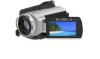
Sony HDR SR5 Service Manual - Page 8
Service Note, 1. Power, Supply, During, Repairs, 2. Self-diagnosis, Function - hdr sr5e manual
 |
UPC - 027242719651
View all Sony HDR SR5 manuals
Add to My Manuals
Save this manual to your list of manuals |
Page 8 highlights
1. SERVICE NOTE ENGLISH JAPANESE 1-1. POWER SUPPLY DURING REPAIRS In this unit, about 10 seconds after power is supplied to the battery terminal using the regulated power supply (8.4V), the power is shut off so that the unit cannot operate. These following method is available to prevent this. Method: Use the AC power adaptor (AC-L200/L200B). 1-2. SELF-DIAGNOSIS FUNCTION 1-2-1. Self-diagnosis Function When problems occur while the unit is operating, the self-diagnosis function starts working, and displays on the Viewfinder or the LCD screen what to do. This function consists of two display; selfdiagnosis display and service mode display. Details of the self-diagnosis functions are provided in the Instruction manual. Viewfinder or LCD screen C : 3 1 : 1 1 1-2-2. Self-diagnosis Display When problems occur while the unit is operating, the counter of the Viewfinder or the LCD screen shows a 4-digit display consisting of an alphabet and numbers, which blinks at 3.2 Hz. This 5-character display indicates the "repaired by:", "block" in which the problem occurred, and "detailed code" of the problem. Blinks at 3.2Hz C 31 11 Repaired by: Block Detailed Code C : Corrected by customer H : Corrected by dealer E : Corrected by service engineer Indicates the appropriate step to be taken. E.g. 31 ....Reload the tape. 32 ....Turn on power again. Refer to "1-2-3. Self-diagnosis Code Table". HDR-SR5/SR5C/SR5E/SR7/SR7E/SR8/SR8E_L2 1-1
-
 1
1 -
2
-
 3
3 -
 4
4 -
 5
5 -
 6
6 -
 7
7 -
 8
8 -
 9
9 -
 10
10 -
 11
11 -
 12
12 -
 13
13 -
14
-
15
-
16
-
17
-
18
-
19
-
20
-
21
-
22
-
23
-
24
-
25
-
26
-
27
-
28
-
29
-
30
-
31
-
32
-
33
-
34
-
35
-
36
-
37
-
38
-
39
-
40
-
41
-
42
-
43
-
44
-
45
-
46
-
47
-
48
-
49
-
50
-
51
-
52
-
53
-
54
-
55
-
56
-
57
-
58
-
59
-
60
-
61
-
62
-
63
-
64
-
65
-
66
-
67
-
68
-
69
-
70
-
71
-
72
-
73
-
74
-
75
-
76
-
77
-
78
-
79
-
80
-
81
-
82
-
83
-
84
-
85
-
86
-
87
-
88
-
89
-
90
-
91
-
92
-
93
-
94
-
95
-
96
-
97
-
98
-
99
-
100
-
101
-
102
-
103
-
104
-
105
-
106
-
107
-
108
-
109
-
110
-
111
-
112
-
113
-
114
-
115
-
116
-
117
-
118
 |
 |
