Thermador UCVM30FS Installation Instructions - Page 11
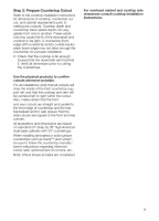
Step 3: Prepare Duct Cutouts in, Cabinet
 |
View all Thermador UCVM30FS manuals
Add to My Manuals
Save this manual to your list of manuals |
Page 11 highlights
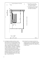
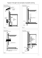
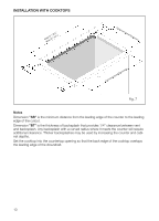
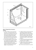
Point "P" Center Line (CL)/ Plumline Fig. 8 Step 3: Prepare Duct Cutouts in Cabinet Y A. Refer to Figure 8. Drop a plumb-line from Point "P" at the rear center of the countertop cutout. Mark this point on the bottom of the cabinet below. Construct two reference lines through this point: one should be parallel to the cabinet front and directly below the rear countertop cutout (Line A-A), and the other (Line B-B) should be at right angles to A-A. Y B. Using these reference lines as a base for the measurements, layout the necessary cabinet cutouts needed to implement the planned ductwork route. Where a range of measurements is noted, choose a measurement that allows best clearance from wall studs, floor joists, utilities, or other obstructions. Step 3: Prepare Duct Cutouts in Step 3: Cabinet Y C. Before cutting for ducting, temporarily set intake and cooktop in place and attach integral blower (or duct transition fitting if a remote or inline blower is installed). Refer to steps 6 and 7. Verify that the duct cutouts as marked will match the hardware installation. Adjust the duct cutout as necessary to match hardware installation. Y D. Remove temporarily placed hardware and make cutouts in cabinet to accommodate ductwork installation. Y E. Make all other cabinet modifications needed to provide proper clearances for drawers or removable shelving. Note: Check boxes as tasks are completed. 11
-
 1
1 -
2
-
3
-
4
-
5
-
 6
6 -
 7
7 -
 8
8 -
 9
9 -
 10
10 -
 11
11 -
 12
12 -
 13
13 -
 14
14 -
 15
15 -
 16
16 -
17
-
18
-
19
-
20
-
21
-
22
-
23
-
24
-
25
-
26
-
27
-
28
-
29
-
30
-
31
-
32
-
33
-
34
-
35
-
36
-
37
-
38
-
39
-
40
-
41
-
42
-
43
-
44
-
45
-
46
-
47
-
48
 |
 |
