Toshiba R600 S4202 Maintenance Manual - Page 279
USB board FPC
 |
UPC - 883974167104
View all Toshiba R600 S4202 manuals
Add to My Manuals
Save this manual to your list of manuals |
Page 279 highlights
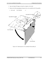
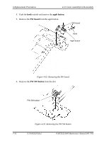
4.20 System board 4 Replacement Procedures Installing the System board To install the system board, follow the steps below and refer to Figure 4-27 and 4-28. 1. Connect the HDD FPC (or SSD FPC), USB board FPC, RJ45 wire harness, sound board FPC and Bluetooth FFC to the connectors CN1900, CN9600, CN4100, CN9500 and CN4400 on the system board. 2. Set the system board in place and connect the LCD harness, membrane switch FPC, keyboard FPC and fingerprint sensor board FFC to the connectors CN5601, CN9850, CN3230 and CN9800 on the system board. 3. Secure the system board with the following screws. • M2×4C S-THIN HEAD ×1 • M3×5C BIND ×2 PORTÉGÉ R600 Maintenance Manual (960-709) [CONFIDENTIAL] 4-51
-
 1
1 -
2
-
3
-
4
-
5
-
6
-
7
-
8
-
9
-
10
-
11
-
12
-
13
-
14
-
15
-
16
-
17
-
18
-
19
-
20
-
21
-
22
-
23
-
24
-
25
-
26
-
27
-
28
-
29
-
30
-
31
-
32
-
33
-
34
-
35
-
36
-
37
-
38
-
39
-
40
-
41
-
42
-
43
-
44
-
45
-
46
-
47
-
48
-
49
-
50
-
51
-
52
-
53
-
54
-
55
-
56
-
57
-
58
-
59
-
60
-
61
-
62
-
63
-
64
-
65
-
66
-
67
-
68
-
69
-
70
-
71
-
72
-
73
-
74
-
75
-
76
-
77
-
78
-
79
-
80
-
81
-
82
-
83
-
84
-
85
-
86
-
87
-
88
-
89
-
90
-
91
-
92
-
93
-
94
-
95
-
96
-
97
-
98
-
99
-
100
-
101
-
102
-
103
-
104
-
105
-
106
-
107
-
108
-
109
-
110
-
111
-
112
-
113
-
114
-
115
-
116
-
117
-
118
-
119
-
120
-
121
-
122
-
123
-
124
-
125
-
126
-
127
-
128
-
129
-
130
-
131
-
132
-
133
-
134
-
135
-
136
-
137
-
138
-
139
-
140
-
141
-
142
-
143
-
144
-
145
-
146
-
147
-
148
-
149
-
150
-
151
-
152
-
153
-
154
-
155
-
156
-
157
-
158
-
159
-
160
-
161
-
162
-
163
-
164
-
165
-
166
-
167
-
168
-
169
-
170
-
171
-
172
-
173
-
174
-
175
-
176
-
177
-
178
-
179
-
180
-
181
-
182
-
183
-
184
-
185
-
186
-
187
-
188
-
189
-
190
-
191
-
192
-
193
-
194
-
195
-
196
-
197
-
198
-
199
-
200
-
201
-
202
-
203
-
204
-
205
-
206
-
207
-
208
-
209
-
210
-
211
-
212
-
213
-
214
-
215
-
216
-
217
-
218
-
219
-
220
-
221
-
222
-
223
-
224
-
225
-
226
-
227
-
228
-
229
-
230
-
231
-
232
-
233
-
234
-
235
-
236
-
237
-
238
-
239
-
240
-
241
-
242
-
243
-
244
-
245
-
246
-
247
-
248
-
249
-
250
-
251
-
252
-
253
-
254
-
255
-
256
-
257
-
258
-
259
-
260
-
261
-
262
-
263
-
264
-
265
-
266
-
267
-
268
-
269
-
270
-
271
-
272
-
273
-
 274
274 -
 275
275 -
 276
276 -
 277
277 -
 278
278 -
 279
279 -
 280
280 -
 281
281 -
 282
282 -
 283
283 -
 284
284 -
285
-
286
-
287
-
288
-
289
-
290
-
291
-
292
-
293
-
294
-
295
-
296
-
297
-
298
-
299
-
300
-
301
-
302
-
303
-
304
-
305
-
306
-
307
-
308
-
309
-
310
-
311
-
312
-
313
-
314
-
315
-
316
-
317
-
318
-
319
-
320
-
321
-
322
-
323
-
324
-
325
-
326
-
327
-
328
-
329
-
330
-
331
-
332
-
333
-
334
-
335
-
336
-
337
-
338
-
339
-
340
-
341
-
342
-
343
-
344
-
345
-
346
-
347
-
348
-
349
-
350
-
351
-
352
-
353
-
354
-
355
-
356
-
357
-
358
-
359
-
360
-
361
-
362
-
363
-
364
-
365
-
366
-
367
-
368
-
369
-
370
-
371
-
372
-
373
-
374
-
375
-
376
-
377
-
378
-
379
-
380
-
381
-
382
-
383
-
384
-
385
-
386
-
387
-
388
-
389
-
390
-
391
-
392
-
393
-
394
-
395
-
396
-
397
-
398
-
399
-
400
-
401
-
402
-
403
-
404
-
405
-
406
-
407
-
408
-
409
-
410
 |
 |

4.20
System board
4 Replacement Procedures
PORTÉGÉ R600 Maintenance Manual (960-709)
[CONFIDENTIAL]
4-51
Installing the System board
To install the system board, follow the steps below and refer to Figure 4-27 and 4-28.
1.
Connect the
HDD FPC
(or
SSD FPC
),
USB board FPC
,
RJ45 wire harness
,
sound
board
FPC
and
Bluetooth FFC
to the connectors
CN1900
,
CN9600
,
CN4100
,
CN9500
and
CN4400
on the system board.
2.
Set the
system board
in place and connect the
LCD harness
,
membrane switch
FPC
,
keyboard
FPC
and
fingerprint sensor board FFC
to the connectors
CN5601
,
CN9850
,
CN3230
and
CN9800
on the system board.
3.
Secure the system board with the following
screws
.
•
M2
×
4C
S-THIN HEAD
×
1
•
M3
×
5C
BIND
×
2