Toshiba R600 S4202 Maintenance Manual - Page 286
antenna cables, insulators
 |
UPC - 883974167104
View all Toshiba R600 S4202 manuals
Add to My Manuals
Save this manual to your list of manuals |
Page 286 highlights
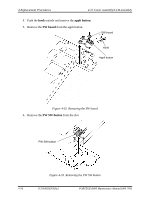
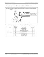
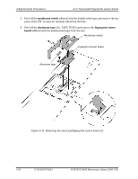
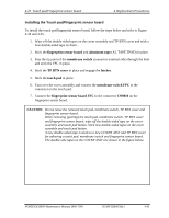
4 Replacement Procedures 4.22 Cover assembly/LCD assembly 5. Arrange the antenna cables in place and fix them with the insulators. CAUTION: Arrange the antenna cables of the lower left portion as shown in the figure below. Do not put the cables on the rib. Please prepare required parts in advance, when replacing the following item. ITEM COVER ASSY Parts List ITEM No 50 20 30 44 06 15 45 70 PART NAME COVER ASSY TOUCH PAD MEMBRANE SWITCH TP BTN COV ASSY PCB ASSY FMTFSx (Fingerprint sensor board) KEYBOARD UNIT INSULATOR KB AL TAPE TPAD Quantity 1 1 1 1 1 1 1 1 4-58 [CONFIDENTIAL] PORTÉGÉ R600 Maintenance Manual (960-709)
-
 1
1 -
2
-
3
-
4
-
5
-
6
-
7
-
8
-
9
-
10
-
11
-
12
-
13
-
14
-
15
-
16
-
17
-
18
-
19
-
20
-
21
-
22
-
23
-
24
-
25
-
26
-
27
-
28
-
29
-
30
-
31
-
32
-
33
-
34
-
35
-
36
-
37
-
38
-
39
-
40
-
41
-
42
-
43
-
44
-
45
-
46
-
47
-
48
-
49
-
50
-
51
-
52
-
53
-
54
-
55
-
56
-
57
-
58
-
59
-
60
-
61
-
62
-
63
-
64
-
65
-
66
-
67
-
68
-
69
-
70
-
71
-
72
-
73
-
74
-
75
-
76
-
77
-
78
-
79
-
80
-
81
-
82
-
83
-
84
-
85
-
86
-
87
-
88
-
89
-
90
-
91
-
92
-
93
-
94
-
95
-
96
-
97
-
98
-
99
-
100
-
101
-
102
-
103
-
104
-
105
-
106
-
107
-
108
-
109
-
110
-
111
-
112
-
113
-
114
-
115
-
116
-
117
-
118
-
119
-
120
-
121
-
122
-
123
-
124
-
125
-
126
-
127
-
128
-
129
-
130
-
131
-
132
-
133
-
134
-
135
-
136
-
137
-
138
-
139
-
140
-
141
-
142
-
143
-
144
-
145
-
146
-
147
-
148
-
149
-
150
-
151
-
152
-
153
-
154
-
155
-
156
-
157
-
158
-
159
-
160
-
161
-
162
-
163
-
164
-
165
-
166
-
167
-
168
-
169
-
170
-
171
-
172
-
173
-
174
-
175
-
176
-
177
-
178
-
179
-
180
-
181
-
182
-
183
-
184
-
185
-
186
-
187
-
188
-
189
-
190
-
191
-
192
-
193
-
194
-
195
-
196
-
197
-
198
-
199
-
200
-
201
-
202
-
203
-
204
-
205
-
206
-
207
-
208
-
209
-
210
-
211
-
212
-
213
-
214
-
215
-
216
-
217
-
218
-
219
-
220
-
221
-
222
-
223
-
224
-
225
-
226
-
227
-
228
-
229
-
230
-
231
-
232
-
233
-
234
-
235
-
236
-
237
-
238
-
239
-
240
-
241
-
242
-
243
-
244
-
245
-
246
-
247
-
248
-
249
-
250
-
251
-
252
-
253
-
254
-
255
-
256
-
257
-
258
-
259
-
260
-
261
-
262
-
263
-
264
-
265
-
266
-
267
-
268
-
269
-
270
-
271
-
272
-
273
-
274
-
275
-
276
-
277
-
278
-
279
-
280
-
 281
281 -
 282
282 -
 283
283 -
 284
284 -
 285
285 -
 286
286 -
 287
287 -
 288
288 -
 289
289 -
 290
290 -
 291
291 -
292
-
293
-
294
-
295
-
296
-
297
-
298
-
299
-
300
-
301
-
302
-
303
-
304
-
305
-
306
-
307
-
308
-
309
-
310
-
311
-
312
-
313
-
314
-
315
-
316
-
317
-
318
-
319
-
320
-
321
-
322
-
323
-
324
-
325
-
326
-
327
-
328
-
329
-
330
-
331
-
332
-
333
-
334
-
335
-
336
-
337
-
338
-
339
-
340
-
341
-
342
-
343
-
344
-
345
-
346
-
347
-
348
-
349
-
350
-
351
-
352
-
353
-
354
-
355
-
356
-
357
-
358
-
359
-
360
-
361
-
362
-
363
-
364
-
365
-
366
-
367
-
368
-
369
-
370
-
371
-
372
-
373
-
374
-
375
-
376
-
377
-
378
-
379
-
380
-
381
-
382
-
383
-
384
-
385
-
386
-
387
-
388
-
389
-
390
-
391
-
392
-
393
-
394
-
395
-
396
-
397
-
398
-
399
-
400
-
401
-
402
-
403
-
404
-
405
-
406
-
407
-
408
-
409
-
410
 |
 |

4 Replacement Procedures
4.22 Cover assembly/LCD assembly
5.
Arrange the
antenna cables
in place and fix them with the
insulators
.
CAUTION
:
Arrange the antenna cables of the lower left portion as shown in the figure
below.
Do not put the
cables on the rib.
Please prepare required parts in advance, when replacing the following item.
ITEM
Parts List
ITEM No
PART NAME
Quantity
50
COVER ASSY
1
20
TOUCH PAD
1
30
MEMBRANE SWITCH
1
44
TP BTN COV ASSY
1
06
PCB ASSY FMTFSx
(Fingerprint sensor board)
1
15
KEYBOARD UNIT
1
45
INSULATOR KB
1
COVER ASSY
70
AL TAPE TPAD
1
4-58
[CONFIDENTIAL]
PORTÉGÉ R600 Maintenance Manual (960-709)