ViewSonic VX710 Service Manual
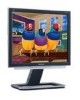
ViewSonic VX710 - 17" LCD Monitor Manual
 |
UPC - 766907022612
View all ViewSonic VX710 manuals
Add to My Manuals
Save this manual to your list of manuals |
ViewSonic VX710 manual content summary:
- ViewSonic VX710 | Service Manual - Page 1
Service Manual ViewSonic VX710-1 Model No. VS10049 17" Color TFT LCD Display (VX710_SM_820 Rev. 1d Apr. 2005) ViewSonic“ 381 Brea Canyon Road, Walnut, California 91789 USA - (800) 888-8583 - ViewSonic VX710 | Service Manual - Page 2
, mechanical, magnetic, optical, chemical, manual or otherwise, without the prior written permission of ViewSonic Corporation. Disclaimer ViewSonic makes no representations or warranties, either expressed or implied, with respect to the contents hereof and specifically disclaims any warranty of - ViewSonic VX710 | Service Manual - Page 3
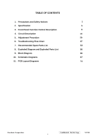
14 5. Adjustment Procedure 25 6. Troubleshooting Flow Chart 47 7. Recommended Spare Parts List 53 8. Exploded Diagram and Exploded Parts List 56 9. Block Diagram 66 10. Schematic Diagrams 67 11. PCB Layout Diagrams 74 ViewSonic Corporation Confidential - Do Not Copy VX710 ii - ViewSonic VX710 | Service Manual - Page 4
4. LCD Module Handling Precautions 4.1 Handling Precautions (1) Since front polarizer is easily damaged, pay attention not to scratch it. (2) Be sure to turn off power supply when rotate or tilt the Interface Connector of the TFT Module. ViewSonic Corporation Confidential - Do Not Copy VX710 1 - ViewSonic VX710 | Service Manual - Page 5
an enclosure (LCD monitor housing, for Power Source (IEC60950 or UL1950), or an exemption should be applied for. (14) The LCD module is designed so that the CCFL in it is supplied by a Limited Current Circuit (IEC60950 or UL1950). Do not connect the CCFL to a Hazardous Voltage Circuit. ViewSonic - ViewSonic VX710 | Service Manual - Page 6
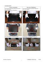
of the polarizer . Incorrect Methods : If the surface of the panel is pressed by fingers, this may cause "MURA." Take out the monitor by grasping the cushion. If the monitor is removed by grasping the LCD panel, that may cause "MURA." ViewSonic Corporation Confidential - Do Not Copy VX710 3 - ViewSonic VX710 | Service Manual - Page 7
Correct Methods : Place the monitor on a clean & soft foam pad . Incorrect Methods : If the monitor is placed on foreign objects, that could scratch the surface of the panel. ViewSonic Corporation Confidential - Do Not Copy VX710 4 - ViewSonic VX710 | Service Manual - Page 8
Impedance Maximum PC Video Signal Maximum Mac Video Signal Sync Signals DDC 1/2B Video Compatibility Resolution Compatibility Exclusions 2.3. POWER Power Supply Internal Power Supply Input Voltage Range Input Frequency Range Short Circuit Protection Over Current Protection Leakage Current EFFICIENCY - ViewSonic VX710 | Service Manual - Page 9
x 768 @ 60Hz, 48.4kHz 15. 1024 x 768 @ 70Hz, 56.5kHz 16. 1024 x 768 @ 72Hz, 58.1kHz 17. 1024 x 768 @ 75Hz, 60.0kHz 18. 1024 x 768 @ 85Hz, 68.67kHz 19. 1280 x 1024 @ 60Hz, 63 timing . The image shall blank while the monitor changes modes. ViewSonic Corporation Confidential - Do Not Copy VX710 6 - ViewSonic VX710 | Service Manual - Page 10
2.5. LCD PANEL 1st Source Panel Model number Type Active Size Pixel Arrangement Pixel Pitch GLASS TREATMENT # OF BACKLIGHTS BACKLIGHT LIFE Luminance (Center) - (Tr= 2 ms, Tf = 6 ms) (typ) 16 ms (max) Please see Panel Quality Specifications. ViewSonic Corporation Confidential - Do Not Copy VX710 7 - ViewSonic VX710 | Service Manual - Page 11
(Base attached unless otherwise specified) Width Height Depth Depth (Head Only) Monitor Weight Packaging Specification Width Height Depth Gross Weight # units per Pallet 20'/40' Container -Condensing 0 to +3,000 meters 0 to +12,000 meters ViewSonic Corporation Confidential - Do Not Copy VX710 8 - ViewSonic VX710 | Service Manual - Page 12
screen. Displays the control screen for the highlighted control. Also toggles between two controls on some screens. Also a shortcut to toggle analog and digital connection. Power light Green = ON Orange = Power Saving Standby Power On/Off ViewSonic Corporation Confidential - Do Not Copy VX710 - ViewSonic VX710 | Service Manual - Page 13
signal 1280 x 1024 @ 60Hz to the LCD display. (Look for instructions on "changing the refresh rate" in your graphic card's user guide.) • If necessary, make small adjustments using H. POSITION and V. POSITION until the screen image is completely visible. (The black border around the edge of the - ViewSonic VX710 | Service Manual - Page 14
the resolution to its pre-set value. 2. The Auto Image Adjust and most Manual Image Adjust functions are not available for DVI input. Contrast adjusts the difference between the image background (black level) and the foreground (white level). Brightness adjusts background black level of the screen - ViewSonic VX710 | Service Manual - Page 15
your graphic card's user guide for instructions on changing the resolution and refresh rate (vertical frequency). NOTE: VESA 1280 x 1024 @ 60 Hz (recommended) means that the resolution is 1280 x 1024 and the refresh rate is 60 Hertz. Manual Image Adjust displays the Manual Image Adjust menu. The - ViewSonic VX710 | Service Manual - Page 16
to the original factory settings if the display is operating in a factory Preset Timing Mode listed in this user guide. Exception: This control does not affect changes made with the User Color control, Language and Power Lock setting. ViewSonic Corporation Confidential - Do Not Copy VX710 13 - ViewSonic VX710 | Service Manual - Page 17
on the front panel: Power On/Off button, button Audio Adjust Color Adjust Information Manual Image Adjust Setup Menu Memory Recall 2 6 1 DB15HD 16 17 15 14 13 12 11 3. Electrical Specifications 3.1 Standard conditions Display Area ViewSonic Corporation Confidential - Do Not Copy VX710 14 - ViewSonic VX710 | Service Manual - Page 18
3.2 Power 3.2.1 Power supply Input Voltage Power Frequency Input current Inrush current Power consumption Output Voltage 90 -240 ~Volts 50/ 60 Hz +/-3Hz - ViewSonic VX710 | Service Manual - Page 19
of Manufacture = 01 (17) Year of Manufacture = 2005 (10-17) Complete Serial Number = Power Management and Supported Feature(s): Active Off/Very Low Power, Standard Default Color Space, Preferred Timing Mode Display Type = R/G/B Color ViewSonic Corporation Confidential - Do Not Copy VX710 - ViewSonic VX710 | Service Manual - Page 20
: 1024 lines Blanking Time: 42 lines Sync Offset: 1 lines Sync Pulse Width: 3 lines Border: 0 lines Frequency: 60.02 Hz Digital Separate, Horizontal Polarity (+) Vertical Polarity ViewSonic Corporation Confidential - Do Not Copy VX710 17 - ViewSonic VX710 | Service Manual - Page 21
Max Vertical Freq - 85 Hz Min Horiz. Freq - 30 KHz Max Horiz. Freq - 82 KHz Pixel Clock - 140 MHz Secondary GTF - Not Supported 108-125) Detailed Timing / Descriptor Block 4: Monitor Name: VX710 (126) (127) No Extension EDID Block(s) CheckSum OK ViewSonic Corporation Confidential - Do Not Copy - ViewSonic VX710 | Service Manual - Page 22
MANAGEMENT AND SUPPORTED FEATURE(S): ACTIVE OFF/VERY LOW POWER, STANDARD DEFAULT COLOR SPACE, PREFERRED TIMING MODE DISPLAY TYPE = R/G/B COLOR CHROMA INFO: RED X - 0.639 GREEN X - 0.287 BLUE X - 0.141 WHITE X - 0.313 RED Y - 0.344 GREEN Y - 0.615 BLUE Y - 0.087 WHITE Y - 0.329 ViewSonic Corporation - ViewSonic VX710 | Service Manual - Page 23
: 1024 LINES SYNC OFFSET: 1 LINES BORDER: 0 LINES BLANKING TIME: 42 LINES SYNC PULSE WIDTH: 3 LINES FREQUENCY: 60.02 HZ DIGITAL SEPARATE, HORIZONTAL POLARITY (+) VERTICAL POLARITY ViewSonic Corporation Confidential - Do Not Copy VX710 20 - ViewSonic VX710 | Service Manual - Page 24
MAX VERTICAL FREQ - 85 HZ MIN HORIZ. FREQ - 30 KHZ MAX HORIZ. FREQ - 82 KHZ PIXEL CLOCK - 140 MHZ SECONDARY GTF - NOT SUPPORTED 108-125) DETAILED TIMING / DESCRIPTOR BLOCK 4: MONITOR NAME: VX710 (126) (127) NO EXTENSION EDID BLOCK(S) CHECKSUM OK ViewSonic Corporation Confidential - Do Not Copy - ViewSonic VX710 | Service Manual - Page 25
LCD monitor per functional block. This monitor includes MB board, power board and button board. 6.1 MB BOARD The MB board is a two-layer, single-grounded design with ground and internal planes provided. DC power from the power definitions. ViewSonic Corporation Confidential - Do Not Copy VX710 22 - ViewSonic VX710 | Service Manual - Page 26
and 2 ( Pin32 and Pin3) to control LCD power sequencing once data and control signals are stable. f) Panel interface (Pin73~94): The RTD2523 driver interface is highly programmable. It supports dual bus / dual port for SXGA drivers. 6.1.2 Power Regulator AIC1563 (U2), AIC1117CY (U1,U3): The - ViewSonic VX710 | Service Manual - Page 27
specific power (inverter) board for VX912 monitor with output of 40W / 12V / 3.5A. It provides 12 VDC to drive the four cold cathode fluorescence tubes in the backlight. 6.2.1 The inverter's electrical specification 120mVp-p - ViewSonic VX710 | Service Manual - Page 28
page. Red, Green, Blue Options: Press the [2] button to cycle among the colors. Press the [1] button to exit the page. Press the [▲] button to increase the selected color level. Press the [▼] button to decrease the selected color level. ViewSonic Corporation Confidential - Do Not Copy VX710 25 - ViewSonic VX710 | Service Manual - Page 29
page. Press the [1] button to exit the information page. (6) Manual Image Adjust Page: Press the [2] button to enter the manual image adjustment page. Press the [1] button to exit the page [2] button to enter the language selection page. ViewSonic Corporation Confidential - Do Not Copy VX710 26 - ViewSonic VX710 | Service Manual - Page 30
the language. Press the [1] button to exit the page. 2) Resolution Notice Item Press the [2] button to enter the resolution notice page. Press the [1] button to exit the page. Enable, function. Press the [1] button to exit the page. ViewSonic Corporation Confidential - Do Not Copy VX710 27 - ViewSonic VX710 | Service Manual - Page 31
page. (3) Input Select Page: Press the [2] button to switch to analog input mode. (4) Color Adjust Page: Press the [2] button to enter the color adjustment page. ViewSonic Corporation Confidential - Do Not Copy VX710 28 - ViewSonic VX710 | Service Manual - Page 32
User Color Item Press the [2] button to enter the user color page. Press the [1] button to exit the page. Red, Green, Blue Options: Press the [2] button to cycle Resolution Notice Item Press the [2] button to enter the resolution notice page. ViewSonic Corporation Confidential - Do Not Copy VX710 - ViewSonic VX710 | Service Manual - Page 33
the Contrast Dialog. Press the [2] button to enter the Brightness Dialog. Press the [▲] button to increase the contrast. Press the [▼] button to decrease the contrast. ViewSonic Corporation Confidential - Do Not Copy VX710 30 - ViewSonic VX710 | Service Manual - Page 34
rate is greater than than 85Hz or its resolution is greater than SXGA, the "Out of Range" message will appear in the center of the screen. Activating Factory Mode and Burn Mode: While the device is in standby, press the [2] button, then press the power button to enter Factory Mode. While Factory - ViewSonic VX710 | Service Manual - Page 35
resolution ) (2) Test condition Warm-up at least 30mins is necessary under following condition before function test & alignment : 1. room temperature 2. With full-white screen , RGB , black pattern 3. with cycled 75Hz, 49.7kHz 17 1024 x 768 ViewSonic Corporation Confidential - Do Not Copy VX710 32 - ViewSonic VX710 | Service Manual - Page 36
& performance 2 Monitor saturation 3 RGB color performance 4 Sub-pixel defect 5 Full white 6 Full black 7. 5-cycle pattern 8. 1-dot pattern Pattern Cross-hatch pattern 16-gray scale pattern RGB color RGB color Full white Full black 5-cycle pattern 1-dot pattern Specification No noise is - ViewSonic VX710 | Service Manual - Page 37
Pattern 5 Pattern 7 Pattern 9 Pattern 6 Pattern 8 ViewSonic Corporation Confidential - Do Not Copy VX710 34 - ViewSonic VX710 | Service Manual - Page 38
monitor , please check whether the firmware version. If not , please following procedure to upgrade to the latest version . 1. Equipment needed : - VX710 - PC ( Personal computer ) - LPT cable - Fixture (LM5ISP) - Firmware upgrade program ViewSonic Corporation Confidential - Do Not Copy VX710 - ViewSonic VX710 | Service Manual - Page 39
2. Connection : To PC To Monitor Appendix A : How to install the software for ISP: 1. To set up ISP environment: Hardware: PC or notebook, program, please adjust the BIOS settings in the PC or notebook as shown in Fig 0.0. ViewSonic Corporation Fig 0.0 Confidential - Do Not Copy VX710 36 - ViewSonic VX710 | Service Manual - Page 40
2. Double-click the "PORT95NT.exe" icon in Windows and install the program; see Fig 0.1. Fig 0.1 3. Continue through the installation process by pressing "Next" four times; see Fig. 0.2. ViewSonic Corporation Fig. 0.2 Confidential - Do Not Copy VX710 37 - ViewSonic VX710 | Service Manual - Page 41
4. Choose "Typical" then press "Next;" see Fig. 0.3. Fig. 0.3 5. Continue through the installation process by pressing "Next" four times; see Fig. 0.4. ViewSonic Corporation Fig. 0.4 38 Confidential - Do Not Copy VX710 - ViewSonic VX710 | Service Manual - Page 42
ISP 1. The user may download the ISP driver and PORT95NT installation package from the Myson Century website (www.myson.com.) 2. The files extracted from the ZIP file are listed in Fig 1.0. Double-click setup.exe to install. ViewSonic Corporation Fig 1.0 39 Confidential - Do Not Copy VX710 - ViewSonic VX710 | Service Manual - Page 43
3. Press the "Next" button to continue; see Fig 1.1. Fig 1.1 4. Press the "Change" button to change the install path if desired, and then press the "Next" button to continue; see Fig 1.2. ViewSonic Corporation Fig 1.2 40 Confidential - Do Not Copy VX710 - ViewSonic VX710 | Service Manual - Page 44
5. Press the "Install" button to continue; see Fig 1.3. Fig. 1.3 6. When installation has finished, press the "Finish" button; see Fig 1.4. ViewSonic Corporation Fig. 1.4 41 Confidential - Do Not Copy VX710 - ViewSonic VX710 | Service Manual - Page 45
security file is a key to use ISP functions; press the "OK" button. See Fig 2.2. Fig. 2.2 3. The warning shown in Fig. 2.3 is used to remind the user that a CPU rate that differs from IIC protocol may cause the ISP functions to fail; press the "OK" button - ViewSonic VX710 | Service Manual - Page 46
4. As shown in Fig. 2.4, press the "Create Security File" button to key in a security code, and use the slider bar to adjust the speed of the IIC bus. Speed of IIC bus Fig. 2.4 Security code ViewSonic Corporation Confidential - Do Not Copy VX710 43 - ViewSonic VX710 | Service Manual - Page 47
requires two command numbers, and the commands must be keyed in sequentially: 7C, 4C, 77. The command numbers and commands must be set by the user while coding. For more details, please refer to section 6 boot code of ISP. Fig. 2.5 ViewSonic Corporation Confidential - Do Not Copy VX710 44 - ViewSonic VX710 | Service Manual - Page 48
Appendix C: Using ISP to program MCU 1. As shown in Fig. 3.1, select the MTV type first, load the binary or intel hex file to be programmed into the MCU, click "OK," then press the "RUN" button. Step 2 Step 1 Step 4 Step 3 Fig. 3.1 ViewSonic Corporation Confidential - Do Not Copy VX710 45 - ViewSonic VX710 | Service Manual - Page 49
2. If the user changes the MTV type, the file must be loaded again, as the previously loaded file will be cleared. 3. CRC ( flash. The Check MCU CRC OK message indicates that the host has verified the program's CRC; see Fig.3.2. Fig. 3.2 ViewSonic Corporation Confidential - Do Not Copy VX710 46 - ViewSonic VX710 | Service Manual - Page 50
6. Troubleshooting Flow Chart 1. Display color abnormal: ViewSonic Corporation Confidential - Do Not Copy VX710 47 - ViewSonic VX710 | Service Manual - Page 51
2.. Monitor can not power on ViewSonic Corporation Confidential - Do Not Copy VX710 48 - ViewSonic VX710 | Service Manual - Page 52
3. Monitor white screen ViewSonic Corporation Confidential - Do Not Copy VX710 49 - ViewSonic VX710 | Service Manual - Page 53
4. Monitor black screen ViewSonic Corporation Confidential - Do Not Copy VX710 50 - ViewSonic VX710 | Service Manual - Page 54
5. Analog input: always shows NO SIGNAL: ViewSonic Corporation Confidential - Do Not Copy VX710 51 - ViewSonic VX710 | Service Manual - Page 55
6. Digital input: always shows NO SIGNAL ViewSonic Corporation Confidential - Do Not Copy VX710 52 - ViewSonic VX710 | Service Manual - Page 56
board Power board Power board Back cover assy Front bezel assy Cable for MB-BB (8P, Rev1A) Cable for MB-LCD (30P. Rev.1A) User's manual + CD wizard User's manual + CD wizard User's manual + CD wizard 17" LGL TFT LCD panel 17" LGL TFT LCD panel (2nd source) 17" AUO TFT LCD panel 17" QDI TFT LCD panel - ViewSonic VX710 | Service Manual - Page 57
ViewSonic P/N #N/A B-00002461 #N/A #N/A #N/A Ref. P/N 1L7VDZQVS02 29L9IMB00D7 L9I204-01 39L9IDP0005 41L9ISS0002 6 #N/A CC62204MD23 BOM LIST (VX710-1) Description L7VD-Q LCD MONITOR DFDI30FR049 CONN DVI-I DIP30P 3R FR(P1.905,H10.04) 17 M-MS-0808-9809 DFHD30MR259 CONN DIP HEADER 30P 2R MR(P2 - ViewSonic VX710 | Service Manual - Page 58
/15P,REV1A) POWER CORD 3P 1.8M LCD FILM L7VC(JXL7V003,REV3B) HI-POT LABEL L70L(HCL70021,REV3A) SPACE PLATE L7VD(HFL7V011,REV3A) 8MS STICKER L7VC(HCL7V028,REV3A) Location Universal No. Qty 2 1 1 1 2 1 1 1 1 1 1 1 1 1 1 1 1 1 1 1 1 1 1 0.05 1 ViewSonic Corporation Confidential - Do Not Copy VX710 - ViewSonic VX710 | Service Manual - Page 59
8. Exploded Diagram And Spare Parts List ViewSonic Corporation Confidential - Do Not Copy VX710 56 - ViewSonic VX710 | Service Manual - Page 60
EXPLODED PARTS LIST (VX710-1) ViewSonic Model Number: VS10049 Rev: 1d Item ViewSonic P/N Ref. P/N Description Qty 1 C-FP-0301-0992 7 M-BK-0805-0077 FBL7V038014 LCD-BKT-L 1 8 E-00002216 AA17EL07055 LCD(TFT)17" QD17EL07 V.9 SVGA 1 9 M-BK-0805-0078 FBL7V039011 LCD-BKT-R 1 10 M-SCW- - ViewSonic VX710 | Service Manual - Page 61
PACKING PARTS LIST (VX710-1) ViewSonic Model Number: VS10049 Rev: 1c Item ViewSonic P/N Ref. P/N Description Qty 1 VX710 1L7VDZQVS02 VX710 unit 1 2 P-FM-0602-0875 HBL7V007011 END CAP(L) 1 3 P-FM-0602-0876 HBL7V008018 END CAP(R) 1 4 DC-00002462 HGL7V014012 User manual & CD - ViewSonic VX710 | Service Manual - Page 62
Packing procedure 1. Apply protective film to the display surface. 2. Put the monitor in EPE bag and seal the bag with tape. 3. Fit the cushions onto the monitor. ViewSonic Corporation Confidential - Do Not Copy VX710 59 - ViewSonic VX710 | Service Manual - Page 63
4. Put the monitor into the carton and put all the accessories into the carton. Then close the carton. QSG Power cord Disassembling the monitor 1. Turn the monitor to face the back and remove the I/O cover. 2. Remove the stand back cover. ViewSonic Corporation Confidential - Do Not Copy VX710 60 - ViewSonic VX710 | Service Manual - Page 64
3. Remove the four black hinge screws and separate the stand and head pieces. 4. Place the monitor face-down on a soft, flat, stable surface. 5. Separate the back cover and the front bezel. ViewSonic Corporation Confidential - Do Not Copy VX710 61 - ViewSonic VX710 | Service Manual - Page 65
6. Remove the screws that fix the button board (B/B) and pull the cable out from the connector on the main board (M/B). 7. Remove the B/B. 8. Remove the screws on the PCB shield; remove the PCB shield. ViewSonic Corporation Screws Confidential - Do Not Copy VX710 62 - ViewSonic VX710 | Service Manual - Page 66
9. Remove the MB-LCD connector and loosen the four screws on the PCB holder. Screws 10. Separate the PCB holder from the panel. ViewSonic Corporation Confidential - Do Not Copy VX710 63 - ViewSonic VX710 | Service Manual - Page 67
11. Loosen the four screws on the sides of the panel. 12. Remove the front bezel and panel. ViewSonic Corporation Confidential - Do Not Copy VX710 64 - ViewSonic VX710 | Service Manual - Page 68
13. Remove the four hexagon screws beside the DVI & D-SUB connectors. 14. Remove the screws that fix the power board and main board. ViewSonic Corporation Confidential - Do Not Copy VX710 65 - ViewSonic VX710 | Service Manual - Page 69
VX710 Confidential - Do Not Copy DDC-SCL;DDC-SDA ANALOG RGB HSYNC ,VSYNC AR AG AB Triple ADC Interface DDC 24C02 DVI POWER 12V 12V 5V AIC1563 AIC117ADJ AIC1117ADJ 3.3V 2.5V 66 9. Block Diagram REALTEK RTD2523BLOCK DIAGRAM Backlight Crystal 24.576MHz EEPROM 24C16 ISP Crystal 11.059MHz - ViewSonic VX710 | Service Manual - Page 70
-CONTROLLER MTV312 LCD PANEL(17 19 RSDS AND LVDS) AUDIO_VOLUME BRIGHTNESS INVCTRL AUDIO_MUTE LCDPWR_ON3.3V LCDPWR_ON12V ViewSonic Corporation AC 90-264V POWER INVERTER AND AUDIO BOARD +12V AIC 1563 +5.0V AIC1739 +2.5V AIC1739 +3.3V Confidential - Do Not Copy VX710 67 Title - ViewSonic VX710 | Service Manual - Page 71
R25 100/6 C18 0.047u/6 RED- R26 100/6 C19 0.047u/6 GREEN+ DEL L11,C32,U6,R51,R52 2004/6/17 C20 NC R28 100/6 C21 0.047u/6 GREEN- R29 100/6 C22 0.047u/6 SOGIN R30 1M/6 C24 R31 100/6 B Date: Friday, October 15, 2004 ViewSonic Corporation Confidential - Do Not Copy VX710 68 - ViewSonic VX710 | Service Manual - Page 72
PLL_TEST1 PLL_TEST2 9 12 14 15 17 18 20 21 23 24 TMDS_TST Power 3.3V Power 3.3V Power 3.3V Power 3.3V Power 3.3V Power 3.3V Power 121 110 95 83 71 58 49 RTD2523 SCLK SDIO[0] TCON[4]/SDIO[1] TCON[3]/SDIO2] TCON[2]/SDIO[3]/PWM2 SCSB RESET ViewSonic Corporation Confidential - Do Not Copy VX710 69 - ViewSonic VX710 | Service Manual - Page 73
HSYNC VSYNC P5.0 P5.1 X1 P5.2 P5.3 P5.4 X2 P5.5 P5.6 RESET DA8/HLFHO DA9/HALFV P1.0 P1.1 INT0/P3.2 P1.2 P1.3 P1.4 P3.1/TXD P6.7 P3.0/RXD 3 2 1 42 41 40 34 39 38 17 18 20 21 22 23 24 25 35 36 37 15 28 29 10 15, 2004 ViewSonic Corporation Confidential - Do Not Copy VX710 70 - ViewSonic VX710 | Service Manual - Page 74
10 11 12 13 14 15 16 17 18 19 20 21 22 23 24 25 26 27 28 29 30 13 14 15 16 17 18 19 20 21 10 11 12 13 14 15 16 17 18 19 20 21 22 23 24 10 11 12 13 14 15 16 17 18 19 20 21 22 23 24 13 DGND 15 RXECKIN- 17 RXEIN1- 19 RXEIN2- 21 RXEIN3- 23 13 14 15 16 17 18 19 20 21 L30 must add the part 2004/4/14 C65 - ViewSonic VX710 | Service Manual - Page 75
U9 VS 15 VS 16 AGND C92 0.47U/8/NC C94 0.47U/8/NC 4 INL 9 INR OUTL 17 VAROUT_L 5 C93 SPKOUTL 330U/16V/NC R135 20K/6/NC AGND MUTE MUTE 2 R136 20K/6/NC 3 Size Document Number Rev DISPLAY A Date: Friday, October 15, 2004 ViewSonic Corporation Confidential - Do Not Copy VX710 72 - ViewSonic VX710 | Service Manual - Page 76
CX201209805/8 1N4148 R143 4.7K/6 L28 Q19 C100 0.1u/6 C101 NC/6 3DVCC MMBT3906 R144 4.7K/6 3.3V-->2.5V regulator for 3.3V system power, no 5V 2004/4/14 Title POWER Size Document Number Rev Date: Friday, October 15, 2004 ViewSonic Corporation Confidential - Do Not Copy VX710 73 - ViewSonic VX710 | Service Manual - Page 77
11. PCB Layout Diagrams Main Board Control Board ViewSonic Corporation Confidential - Do Not Copy VX710 74 - ViewSonic VX710 | Service Manual - Page 78
to ViewSonic Corporation. Assessment A. What do you think about the content of this Service Manual? Unit Excellent Good Fair Bad 1. Precautions and Safety Notices 2. Specification 3. Front Panel Function Control Description 4. Circuit Description 5. Adjustment Procedure 6. Troubleshooting
-
 1
1 -
 2
2 -
 3
3 -
 4
4 -
 5
5 -
 6
6 -
 7
7 -
8
-
9
-
10
-
11
-
12
-
13
-
14
-
15
-
16
-
17
-
18
-
19
-
20
-
21
-
22
-
23
-
24
-
25
-
26
-
27
-
28
-
29
-
30
-
31
-
32
-
33
-
34
-
35
-
36
-
37
-
38
-
39
-
40
-
41
-
42
-
43
-
44
-
45
-
46
-
47
-
48
-
49
-
50
-
51
-
52
-
53
-
54
-
55
-
56
-
57
-
58
-
59
-
60
-
61
-
62
-
63
-
64
-
65
-
66
-
67
-
68
-
69
-
70
-
71
-
72
-
73
-
74
-
75
-
76
-
77
-
78
 |
 |

Model No.
VS10049
1
7
”
Color
TFT LCD Display
Service Manual
ViewSonic
VX710
-1
ViewSonic
381 Brea Canyon Road, Walnut, California 91789 USA - (800) 888-8583
(VX710_SM_820 Rev. 1d Apr. 2005)