ViewSonic VX710 Service Manual - Page 17
Circuit Description
 |
UPC - 766907022612
View all ViewSonic VX710 manuals
Add to My Manuals
Save this manual to your list of manuals |
Page 17 highlights
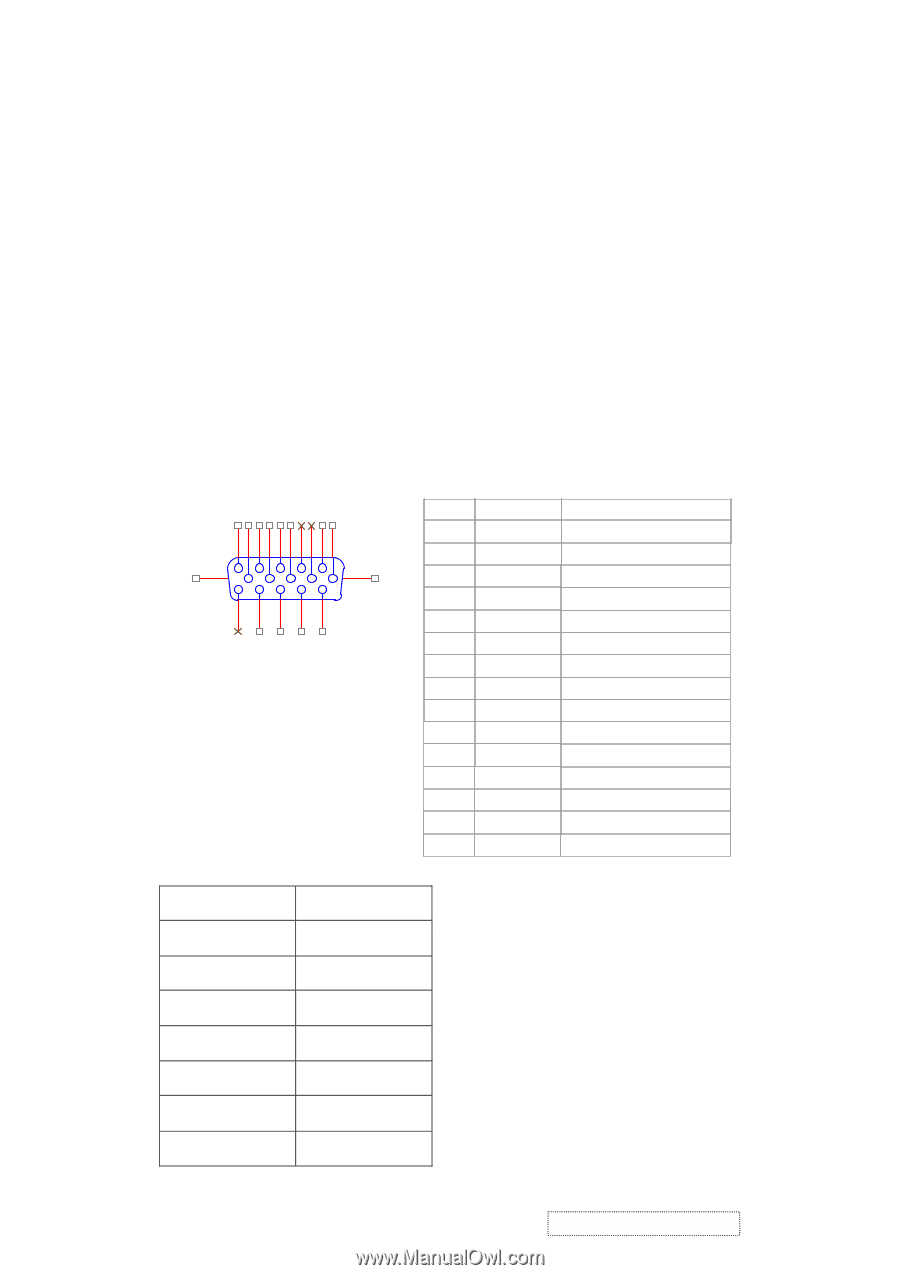
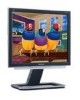
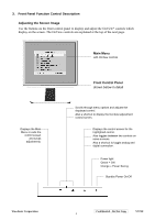
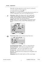
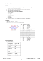
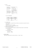
4. Circuit Description 1. Outline 1.1 Buttons on the front panel: Power On/Off button, button 2 (ENTER / INPUT SELECT), up arrow button, down arrow button, button 1 (MENU). 1.2 Video signal connector and AC-IN are located on the back side of the cabinet. 1.3 OSD menu includes the following function; Auto Image Adjust (only active under analog input) Contrast/Brightness Audio Adjust Color Adjust Information Manual Image Adjust Setup Menu Memory Recall 1.4 Contrast and Brightness can be directly controlled with the UP / DOWN buttons. 2. Connectors 2.1 AC Socket: CEE22 type connector 2.2 Video signal connector for analog input: 15P Mini D-Sub CN6 10 5 9 4 8 3 7 2 6 1 DB15HD 16 17 15 14 13 12 11 3. Electrical Specifications 3.1 Standard conditions Display Area Video Signal Contrast Brightness Ambient Input Warming up Display 338 x 270 mm 0.7 Vpp 70% Max. 20 +/- 5 °C AC > 30 min 1280 x 1024 PIN MNEMONIC SIGNAL 1 RV Red Video 2 GV Green Video 3 BV Blue Video 4 NC None 5 GND Ground(DDC return) 6 RG Red GND 7 GG Green GND 8 BG Blue GND 9 +5V + 5V (for DDC) 10 SG Sync GND 11 NC None 12 SDA DDC Data 13 HS Horizontal Sync 14 VS Vertical Sync 15 SCL DDC Clock ViewSonic Corporation Confidential - Do Not Copy VX710 14
-
 1
1 -
2
-
3
-
4
-
5
-
6
-
7
-
8
-
9
-
10
-
11
-
 12
12 -
 13
13 -
 14
14 -
 15
15 -
 16
16 -
 17
17 -
 18
18 -
 19
19 -
 20
20 -
 21
21 -
 22
22 -
23
-
24
-
25
-
26
-
27
-
28
-
29
-
30
-
31
-
32
-
33
-
34
-
35
-
36
-
37
-
38
-
39
-
40
-
41
-
42
-
43
-
44
-
45
-
46
-
47
-
48
-
49
-
50
-
51
-
52
-
53
-
54
-
55
-
56
-
57
-
58
-
59
-
60
-
61
-
62
-
63
-
64
-
65
-
66
-
67
-
68
-
69
-
70
-
71
-
72
-
73
-
74
-
75
-
76
-
77
-
78
 |
 |