ViewSonic VX710 Service Manual - Page 18
Signal Cable - power supply
 |
UPC - 766907022612
View all ViewSonic VX710 manuals
Add to My Manuals
Save this manual to your list of manuals |
Page 18 highlights
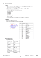
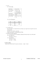
3.2 Power 3.2.1 Power supply Input Voltage Power Frequency Input current Inrush current Power consumption Output Voltage 90 -240 ~Volts 50/ 60 Hz +/-3Hz
-
 1
1 -
2
-
3
-
4
-
5
-
6
-
7
-
8
-
9
-
10
-
11
-
12
-
 13
13 -
 14
14 -
 15
15 -
 16
16 -
 17
17 -
 18
18 -
 19
19 -
 20
20 -
 21
21 -
 22
22 -
 23
23 -
24
-
25
-
26
-
27
-
28
-
29
-
30
-
31
-
32
-
33
-
34
-
35
-
36
-
37
-
38
-
39
-
40
-
41
-
42
-
43
-
44
-
45
-
46
-
47
-
48
-
49
-
50
-
51
-
52
-
53
-
54
-
55
-
56
-
57
-
58
-
59
-
60
-
61
-
62
-
63
-
64
-
65
-
66
-
67
-
68
-
69
-
70
-
71
-
72
-
73
-
74
-
75
-
76
-
77
-
78
 |
 |
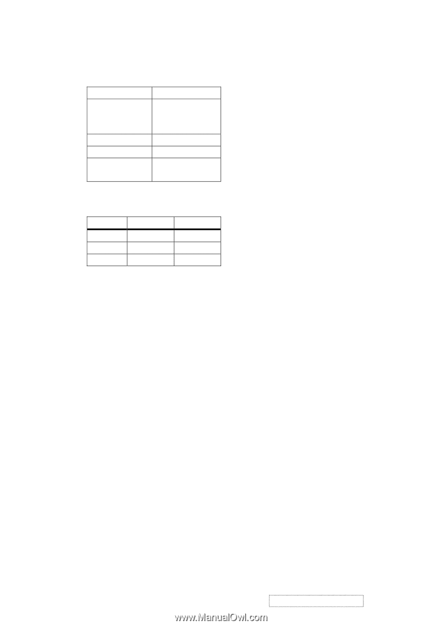
3.2
Power
3.2.1
Power supply
Input Voltage
90 -240 ~Volts
Power Frequency
Input current
50/ 60 Hz +/-3Hz
<1.5Arms @ 90Vac
<0.75Arms@240Vac
Inrush current
90A(max.) at 230Vac
Power consumption
50Watt
Output Voltage
@0-3.0A load 12Vdc
+/-5%
3.2.2
Power Management
State
Power
Indicator
On
40Watt
Green
Standby
<1Watt
Amber
Off
<1Watt
3.3
Acceptable timing
Horizontal: Sync frequency : 30~81 kHz
Vertical: Sync frequency : 56~85Hz(1280x1024,75Hz)
3.4
Signal level and input impedance
3.4.1
Video Signal level This LCD display is adjusted at the factory using 0,7 Vp-p Video signal.
3.4.2
Sync Signal level
H/V Separate : TTL level
3.4.3
Input impedance
Video input : 75 ohms
Sync input : > 1 k ohms
4. SIGNAL CABLE :
Signal cable with Mini D-Sub 15P connectors at both ends.
Length : 1.8 meter.
This LCD display can automatically detect and display input signals whose timing falls within the
following limits.
15
ViewSonic Corporation
Co
nfidential
- Do Not Copy
VX710