ViewSonic VX710 Service Manual - Page 26
Power Regulator AIC1117CY U1,U3: The AIC1117CY is a monolithic control IC containing - driver
 |
UPC - 766907022612
View all ViewSonic VX710 manuals
Add to My Manuals
Save this manual to your list of manuals |
Page 26 highlights
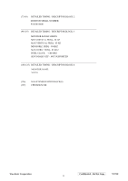
d) MTV312 Micro Controller: The MTV312 micro controller (MCU) serves as the system micro controller. It programs the RTD2523 and manages other devices in the system such as the keypad, the backlight, the LED, the audio system and the non-volatile RAM using general purpose input/output (GPIO) pins. Pin number 1 13 14 41 40 42 34 9 2 27 26 16 17 Pin Name P5.2 P3.4 P3.5 P5.4 P5.5 P5.3 P5.6 P6.3 P5.1 P6.0 P6.1 P6.2 P1.0 Pin Usage Key / Power on, off NV_RAM (U4) SDA NV_RAM (U4) SCL Key_down Key_right Key_up Key_left Key_mute Key_select LED_red LED_green LCD panel power1 on / off control Backlight on / off control e) Panel Power Sequencing (PANEL_PW12,3) (Pin 16, 18): The MTV312 has two dedicated outputs VDDCTRL1 and 2 ( Pin32 and Pin3) to control LCD power sequencing once data and control signals are stable. f) Panel interface (Pin73~94): The RTD2523 driver interface is highly programmable. It supports dual bus / dual port for SXGA drivers. 6.1.2 Power Regulator AIC1563 (U2), AIC1117CY (U1,U3): The AIC1563 is a monolithic control IC containing the primary functions required for DC to DC converters. The device consists of an internal temperature compensated reference, a comparator, and a controlled duty cycle oscillator with an active current sense circuit. The desired output voltage is determined by the equation, Volt = 1.25 (1 + R11 / R12). In this case, the output voltage is 5 Volts. The AIC1563 is a low dropout positive adjustable regulator with minimum of 1A output current capability, so it is well suited to serve as a 3.3 V or 2.5 V regulator. 6.1.3 Power Regulator AIC1117CY (U1,U3): The AIC1117CY is a monolithic control IC containing the primary functions required for DC to DC converters. The device consists of an internal temperature compensated reference, a comparator, and a controlled duty cycle oscillator with an active current sense circuit. The desired output voltage is determined by the equation, Volt = 1.25 (1 + R17 / R15). In this case, the output voltage is 2.5 Volts for panel power. ViewSonic Corporation Confidential - Do Not Copy VX710 23
-
 1
1 -
2
-
3
-
4
-
5
-
6
-
7
-
8
-
9
-
10
-
11
-
12
-
13
-
14
-
15
-
16
-
17
-
18
-
19
-
20
-
 21
21 -
 22
22 -
 23
23 -
 24
24 -
 25
25 -
 26
26 -
 27
27 -
 28
28 -
 29
29 -
 30
30 -
 31
31 -
32
-
33
-
34
-
35
-
36
-
37
-
38
-
39
-
40
-
41
-
42
-
43
-
44
-
45
-
46
-
47
-
48
-
49
-
50
-
51
-
52
-
53
-
54
-
55
-
56
-
57
-
58
-
59
-
60
-
61
-
62
-
63
-
64
-
65
-
66
-
67
-
68
-
69
-
70
-
71
-
72
-
73
-
74
-
75
-
76
-
77
-
78
 |
 |