ViewSonic VX710 Service Manual - Page 25
THEORY OF OPERATION, Pin Name, Pin Number, Green, Green
 |
UPC - 766907022612
View all ViewSonic VX710 manuals
Add to My Manuals
Save this manual to your list of manuals |
Page 25 highlights
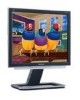
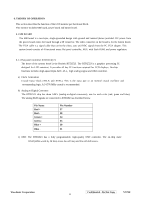
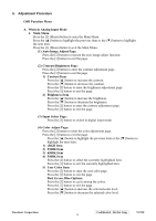
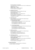
6. THEORY OF OPERATION This section describes the function of the LCD monitor per functional block. This monitor includes MB board, power board and button board. 6.1 MB BOARD The MB board is a two-layer, single-grounded design with ground and internal planes provided. DC power from the power board enters the board through a 6P connector. The other connector on the board is for the button board. The VGA cable is a signal cable that carries the video, sync and DDC signals from the PC VGA adapter. This system board consists of 4 functional areas: flat panel controller, MCU with flash ROM, and power regulators. 6.1.1 Flat panel controller: RTD2523(U7) The heart of the system board is the Realtek RTD2523. The RTD2523 is a graphics processing IC designed for LCD monitors. It provides all key IC functions required for LCD displays. On-chip functions include a high-speed triple-ADC, PLL, high scaling engine and OSD controller. a) Clock Generation: Crystal Input Clock (TCLK and XTAL). This is the input pair to an internal crystal oscillator and corresponding logic. A 24.576 MHz crystal is recommended. b) Analog to Digital Converter: The RTD2523 chip has three ADCs (analog-to-digital converters), one for each color (red, green and blue). The analog RGB signals are connected to RTD2523 as described below. Pin Name Red + Red Green + Green Blue + Blue - Pin Number 37 38 34 35 30 31 c) OSD: The RTD2523 has a fully programmable, high-quality OSD controller. The on-chip static RAM (4096 words by 24 bits) stores the cell map and the cell definitions. ViewSonic Corporation Confidential - Do Not Copy VX710 22
-
 1
1 -
2
-
3
-
4
-
5
-
6
-
7
-
8
-
9
-
10
-
11
-
12
-
13
-
14
-
15
-
16
-
17
-
18
-
19
-
 20
20 -
 21
21 -
 22
22 -
 23
23 -
 24
24 -
 25
25 -
 26
26 -
 27
27 -
 28
28 -
 29
29 -
 30
30 -
31
-
32
-
33
-
34
-
35
-
36
-
37
-
38
-
39
-
40
-
41
-
42
-
43
-
44
-
45
-
46
-
47
-
48
-
49
-
50
-
51
-
52
-
53
-
54
-
55
-
56
-
57
-
58
-
59
-
60
-
61
-
62
-
63
-
64
-
65
-
66
-
67
-
68
-
69
-
70
-
71
-
72
-
73
-
74
-
75
-
76
-
77
-
78
 |
 |
