Weider Pro 5500 User Manual
Weider Pro 5500 Manual
 |
View all Weider Pro 5500 manuals
Add to My Manuals
Save this manual to your list of manuals |
Weider Pro 5500 manual content summary:
- Weider Pro 5500 | User Manual - Page 1
if there are missing or damaged parts, please call: 08457 089 009 Or write: ICON Health & Fitness, Ltd. Unit 4 Revie Road Industrial Estate Revie Road, Beeston Leeds, LS11 8JG UK email: [email protected] CAUTION Read all precautions and instructions in this manual before using this equipment. Save - Weider Pro 5500 | User Manual - Page 2
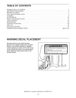
CHART 5 ASSEMBLY 8 ADJUSTMENTS 25 WEIGHT RESISTANCE CHART 27 CABLE DIAGRAM 28 MAINTENANCE 29 EXERCISE GUIDELINES 30 PART LIST 33 EXPLODED DRAWING 34 ORDERING REPLACEMENT PARTS Back Cover WARNING DECAL PLACEMENT The decal shown at the right has been placed on the weight system - Weider Pro 5500 | User Manual - Page 3
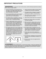
all times. If a cable binds while you are exercising, stop immediately and make sure that the cable is on the pulleys. Replace all cables at least every two years. 5. The weight system has an open weight stack; the weight stack must not be accessible from any point outside the userʼs field of view - Weider Pro 5500 | User Manual - Page 4
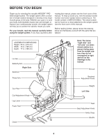
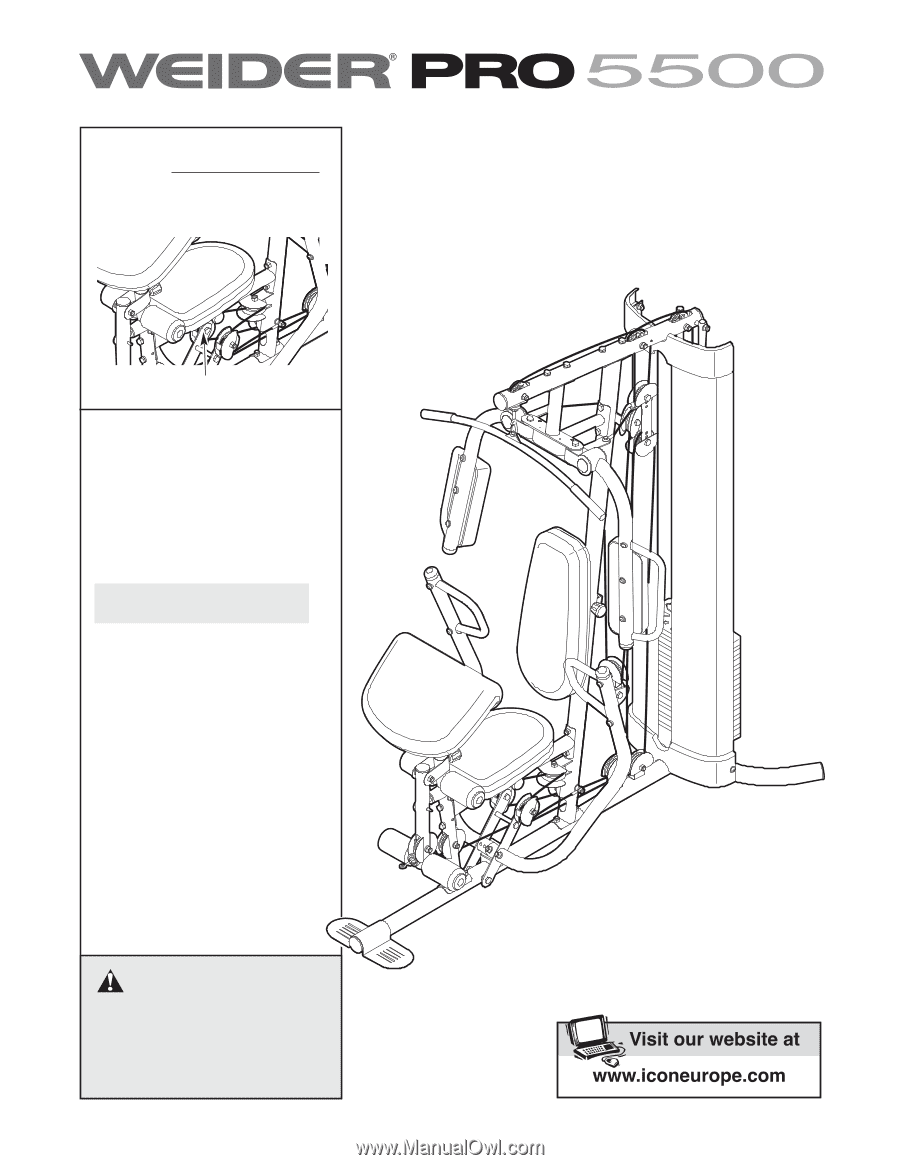
us. The model number is WEEVSY2996.0. The serial number can be found on a decal attached to the weight system (see the front cover of this manual). Before reading further, please review the drawing below and familiarize yourself with the parts that are labeled. ASSEMBLED DIMENSIONS: Height: 83 - Weider Pro 5500 | User Manual - Page 5
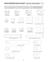
PART IDENTIFICATION CHART-Model No. WEEVSY2996.0 R0706A Refer to the drawings below to identify small parts used in assembly. The number in parentheses by each drawing is the key number of the part, from the PART LIST in the center of this manual. Note: Some small parts may have been preattached. If - Weider Pro 5500 | User Manual - Page 6
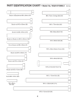
PART IDENTIFICATION CHART-Model No. WEEVSY2996.0 R0706A Boulon à Épaulement M8 x 69mm (87) M8 x 75mm Carriage Bolt (83) Boulon de M10 x 65mm (85) Boulon de M8 x 65mm (101) Boulon en - Weider Pro 5500 | User Manual - Page 7
PART IDENTIFICATION CHART-Model No. WEEVSY2996.0 R0706A Backrest Adjustment Knob (53) Curl Adjustment Knob (58) Seat Adjustment Knob (52) 7 - Weider Pro 5500 | User Manual - Page 8
of this manual. Place the chart on the floor and use it to easily identify parts during each assembly step. Note: Some small parts may have been pre-attached. If a part is not in the parts bag, check to see if it has been pre-attached. How to Orient Parts As you assemble the weight system, make sure - Weider Pro 5500 | User Manual - Page 9
Assembly 1 1. Before beginning assembly, make sure you understand the information in the box on page 8. See the PART IDENTIFICATION CHARTS on pages 5 and 6 of this manual for help identifying small parts Make sure the indicated holes in the Weight Guides are nearer the bottom. Do not tighten - Weider Pro 5500 | User Manual - Page 10
4. Attach the Frame (9) to the Upright (2) with two M8 x 80mm Bolts (100), two M8 Washers (103), and two M8 Nylon Locknuts (78). Do not tighten the Nylon Locknuts yet. Attach the Frame (9) to the Front Leg (10) with two M8 x 65mm Bolts (101), two M8 Washers (103), and two M8 Nylon Locknuts (78). Do - Weider Pro 5500 | User Manual - Page 11
110 104 21 8. Note: Some parts have been removed to show 8 this step clearly. Slide the two Weight Bumpers (71) onto the Weight Guides (18). Orient fourteen Weights (19) with the pin holes on the bottom as shown. Slide the Weights onto the Weight Guides. Insert the Weight Tube (20) into the - Weider Pro 5500 | User Manual - Page 12
Arm Assembly 9 9. Attach the Butterfly Frame Brace (6) to the Upright (2) with two M8 x 80mm Bolts (100), two M8 Washers (103), and two M8 Nylon Locknuts (78). Do - Weider Pro 5500 | User Manual - Page 13
12. Apply grease to the locations shown and attach the Left Butterfly Bracket (28) to the Butterfly 12 Frame (5) with an M10 x 80mm Bolt (84) and an M10 Nylon Locknut (77). 84 Repeat this step for the Right Butterfly Bracket (29). Grease Tighten the Nylon Locknuts (77, 78, 107) used in steps - Weider Pro 5500 | User Manual - Page 14
15. Orient a Press Arm Handle (17) with the 90° bend at the top as shown in the inset drawing. Attach a 15 Press Arm Handle (17) to the Right Press Arm (16) with two M10 x 65mm Button Bolts (106), four M10 Washers (80), four 11mm Spacers (99), and two M10 Nylon Locknuts (77). Repeat this step - Weider Pro 5500 | User Manual - Page 15
28 to identify the cables as you assemble them. Identify the Butterfly Cable (50). Grease an M8 x 22mm Shoulder Bolt (90). Attach the Cable to the Left Butterfly Bracket (28) with the Shoulder Bolt and an M8 Nylon Locknut (78). Make sure the flat edge of the Cable is against the Butterfly Bracket - Weider Pro 5500 | User Manual - Page 16
an M10 Nylon Locknut (77). 21 54 79 57 50 47 80 54 2 77 22. Grease an M8 x 22mm Shoulder Bolt (90). Attach the Butterfly Cable (50) to the Right Butterfly Arm 22 (29) with the Shoulder Bolt and an M8 Nylon Locknut (78). Make sure the flat edge of the - Weider Pro 5500 | User Manual - Page 17
Washer (80), a 19mm Spacer (67), the Top Frame, and the Thin Pulley. 24 84 80 4 49 67 25. Wrap the Lat Cable (49) under a 90mm Pulley (48). Attach the Pulley, a Cable Trap (56), and 25 two Half Guards (55) at the second hole from the top of the two Pulley Plates (60 - Weider Pro 5500 | User Manual - Page 18
80 49 77 4 28. Set an M12 Large Washer (98) on top of the 28 Weight Tube (20). Thread the M12 Nut (112) all the way onto the Lat Cable (49). Thread the Lat Cable (49) into the Weight Tube (20) two turns. Tighten the M12 Nut (112) against the M12 Large Washer (98 - Weider Pro 5500 | User Manual - Page 19
and 31 under the indicated rod in the Base (1). Wrap the Leg Lever Cable under a 90mm Pulley (48). Attach the Pulley to the Base with an M10 51 1 55 77 Rod 32. Wrap the Leg Lever Cable (51) over a 90mm 32 Pulley (48). Attach the Pulley, a Cable Trap (56), and two Half Guards (55) to the - Weider Pro 5500 | User Manual - Page 20
Guards (55), and an M10 Nylon Locknut (77). 34. Wrap the Leg Lever Cable (51) over a 90mm Pulley (48). Attach the Pulley to the Double "U"- 34 Half Guards (55), and an M10 Nylon Locknut (77). 35. Wrap the Leg Lever Cable (51) under a 90mm 35 Pulley (48). Attach the Pulley to the Upright (2) - Weider Pro 5500 | User Manual - Page 21
the Left Press Arm (15) with an M10 x 50mm Bolt (97), two Half Guards (55), an M10 Washer (80), a Cable Trap (56) and an M10 Nylon Locknut (77). Make sure the Cable Trap and Half Guards are oriented as shown. 21 55 2 57 47 77 80 55 51 113 97 51 15 - Weider Pro 5500 | User Manual - Page 22
39. Attach the Leg Lever Cable (51) to the Upright (2) with the M10 x 120mm Bolt (115), an M10 39 Washer (80), a 7mm Spacer (111), and an M10 Nylon Locknut (77). 2 115 80 111 51 77 Seat Assembly 40 26 40. Attach the Right Butterfly Pad (35) to the Right Butterfly Arm (26) with - Weider Pro 5500 | User Manual - Page 23
(37) into each Foam Pad (36). Repeat this step for the other Pad Tube (13) and the Leg Lever (12). Note: Lift the Leg Lever Cable (51) when inserting a Pad Tube into the hole in the bottom of the Leg Lever. 43 37 36 12 51 13 10 13 36 37 - Weider Pro 5500 | User Manual - Page 24
of the remaining parts will be explained in ADJUSTMENTS, beginning on the following page. Before using the weight system, pull each cable a few times to make sure that the cables move smoothly over the pulleys. If one of the cables does not move smoothly, find and correct the problem. IMPORTANT: If - Weider Pro 5500 | User Manual - Page 25
the bent end upward. Note: The weight system works best when at least two Weights are used. 70 19 ATTACHING THE ACCESSORIES To attach the Lat Bar (63) to the Lat Cable (49), attach a Weight Clip (66) to the Lat Cable and the Lat Bar. Note: For some exercises, you will need to attach the Chain - Weider Pro 5500 | User Manual - Page 26
(31) can be adjusted to provide the correct position for each exercise. To adjust the Backrest, loosen but do not remove the Backrest 31 53 32 LOCKING THE WEIGHT STACK To lock the weight stack, insert the Lock Pin (72) through one of the holes in the Weight Guides (18) and secure the Lock - Weider Pro 5500 | User Manual - Page 27
resistance at each exercise station. Note: Weight resistance shown for the butterfly arm station is for each arm. The actual resistance at each station may vary due to differences in individual weight plates as well as friction between the cables, pulleys, and weight guides. For conversion purposes - Weider Pro 5500 | User Manual - Page 28
diagram to make sure that the cable and the cable traps have been assembled correctly. If the cable has not been correctly routed, the weight system will not function properly and damage may occur. The numbers show the correct route for the cable. Make sure that the cable traps do not touch or bind - Weider Pro 5500 | User Manual - Page 29
THE CABLES Woven cable, the type of cable used on the weight system, can stretch slightly when it is first used. If there is slack in the cables before resistance is felt, the cables should be tightened. To tighten the cables, first insert the weight pin into the middle of the weight stack. Slack - Weider Pro 5500 | User Manual - Page 30
only the appropriate parts of the body. Exercising in an uncontrolled manner will leave you feeling exhausted. On the exercise guide accompanying this manual you will find photographs showing the correct form for several exercises, and a list of the muscles affected. See the muscle chart on the next - Weider Pro 5500 | User Manual - Page 31
flexibility. STAYING MOTIVATED For motivation, keep a record of each workout. The chart on page 32 of this manual can be photocopied and used to schedule and record your workouts. List the date, the exercises performed, the weight used, and the numbers of sets and repetitions completed. Record - Weider Pro 5500 | User Manual - Page 32
MONDAY Date: // EXERCISE WEIGHT SETS REPS TUESDAY Date: // WEDNESDAY Date: // AEROBIC EXERCISE EXERCISE WEIGHT SETS REPS THURSDAY Date: // FRIDAY Date: // AEROBIC EXERCISE EXERCISE WEIGHT SETS REPS Make photocopies of this page for scheduling and recording your workouts. 32 - Weider Pro 5500 | User Manual - Page 33
PART LIST-Model No. 115 1 M10 x 120mm Bolt 35 1 Right Butterfly Pad 76 1 Weight Tube Cap 116 1 M10 x 61mm Bolt Set 36 4 Foam Pad 60mm Bolt Screw Cap 80 35 M10 Washer # 1 Userʼs Manual 39 3 50mm Round Inner 81 2 M10 x 85mm Bolt # 1 Exercise Guide Cap 82 2 M10 x 75mm Bolt # 4 Hex - Weider Pro 5500 | User Manual - Page 34
EXPLODED DRAWING-Model No. WEEVSY2996.0 94 114 23 114 107 102 102 114 114 94 110 104 110 21 49 98 19 76 R0706A 112 20 22 19 - Weider Pro 5500 | User Manual - Page 35
EXPLODED DRAWING-Model No. WEEVSY2996.0 R0706A 45 45 84 24 48 74 27 109 106 109 77 74 74 90 50 46 84 80 67100 100 48 103 - Weider Pro 5500 | User Manual - Page 36
the following information: • the MODEL NUMBER of the product (WEEVSY2996.0) • the NAME of the product (WEIDER PRO 5500 weight system) • the SERIAL NUMBER of the product (see the front cover of this manual) • the KEY NUMBER and DESCRIPTION of the part(s) (see the PART LIST and EXPLODED DRAWING in
-
 1
1 -
 2
2 -
 3
3 -
 4
4 -
 5
5 -
 6
6 -
 7
7 -
8
-
9
-
10
-
11
-
12
-
13
-
14
-
15
-
16
-
17
-
18
-
19
-
20
-
21
-
22
-
23
-
24
-
25
-
26
-
27
-
28
-
29
-
30
-
31
-
32
-
33
-
34
-
35
-
36
 |
 |
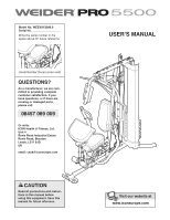
CAUTION
Read all precautions and instruc-
tions in this manual before
using this equipment. Save this
manual for future reference.
Model No. WEEVSY2996.0
Serial No.
Write the serial number in the
space above for future reference.
USERʼS MANUAL
Serial Number Decal (under seat)
QUESTIONS?
As a manufacturer, we are com-
mitted to providing complete
customer satisfaction. If you
have questions, or if there are
missing or damaged parts,
please call:
Or write:
ICON Health & Fitness, Ltd.
Unit 4
Revie Road Industrial Estate
Revie Road, Beeston
Leeds, LS11 8JG
UK
email: [email protected]
08457 089 009