Weider Pro 9655 English Manual
Weider Pro 9655 Manual
 |
View all Weider Pro 9655 manuals
Add to My Manuals
Save this manual to your list of manuals |
Weider Pro 9655 manual content summary:
- Weider Pro 9655 | English Manual - Page 1
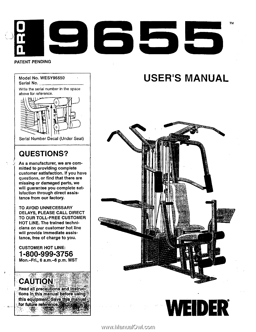
HOT LINE. The trained technicians on our customer hot line will provide immediate assistance, free of charge to you. CUSTOMER HOT LINE: 1-800-999-3756 Mon.-Fri., 6 a.m.-6 p.m. MST CAUTI ,Read all oreceutiOna and instruc Cons inthis manual before using tbls equipmentSave s Minim for future ref( rt - Weider Pro 9655 | English Manual - Page 2
ASSEMBLY HOW TO USE THE HOME GYM SYSTEM WEIGHT RESISTANCE CHART TROUBLE-SHOOTING AND MAINTENANCE CABLE DIAGRAMS ORDERING REPLACEMENT PARTS 2 3 4 5 24 26 27 29 Back Cover Note: A PART IDENTIFICATION CHART and a PART LIST/EXPLODED DRAWING are attached to the center of this manual. Remove the PART - Weider Pro 9655 | English Manual - Page 3
are raised. The weights will fall with great force. 10. Keep hands and feet away from moving parts. Always wear athletic shoes for foot protection. 3 Read all instructions in this manual and in the accompanying literature before using the home gym system. 4 :Use the home gym system only on,a leVe - Weider Pro 9655 | English Manual - Page 4
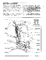
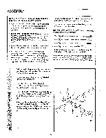
WEIDER® PRO 9655 (see the front cover of this manual). For your benefit, read this manual carefully before using the WEIDER® PRO 9655 Home Gym System. If you have additional questions, please call our Before reading further, please review the drawing below and familiarize yourself with the parts - Weider Pro 9655 | English Manual - Page 5
information and instructions: • Place all parts of the PRO 9655 in a cleared area and remove the packing materials; do not dispose of the packing materials until assembly is completed. • The assembly is broken into four stages: 1) frame assembly, 2) arm assembly, 3) cable and pulley assembly, and - Weider Pro 9655 | English Manual - Page 6
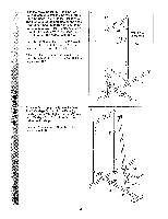
2. Slide the Assist Upright (74) and the Leg Press Upright (56) onto the indicated 5/16" x 2 1/2" Carriage Bolts (1) in the Stabilizer (5). The high side of the brackets on the Assist Upright and Leg Press Upright should be on the side shown. Hand-tighten four 5/16" Nylon Locknuts (3) onto the - Weider Pro 9655 | English Manual - Page 7
25) so that the deeper pin groove in facing the floor. Insert 6 two Weight Bushings (108) into the Weight. Insert two Weight Bushings (108) into each of the remaining twenty-seven Weights (114). 108 'a) I I 25 Deep Pin Groove 7. Note: A 3/8" x 4" Eyebolt (24) and a 3/8" x 7 1 1/2" Screw - Weider Pro 9655 | English Manual - Page 8
Weight Tube (63). Assemble the other Top Weight (65), Weight Cover (71) and Weight Tube (63) in the same manner. Threaded Hole • 63 Set two Weight Bumpers (19) on the bracket on the Base (4) as shown. Set two Weight Bumpers (19) on the bracket on the Stabilizer (5). Insert both Long Weight Guides - Weider Pro 9655 | English Manual - Page 9
10 end of each Weight Tube (63). 0 0 Slide one Weight Cover (71) and Top Weight (inside the Weight Cover) onto the Long 0 Weight Guides (62). Insert the Weight Tube (63) into the front stack of Weights (25). Slide the other Weight Cover (71) onto the 73 Short Weight Guides (73) in the - Weider Pro 9655 | English Manual - Page 10
the Long Weight Guides (62) to the Top Frame (55) in the same manner. 12 61 60 73 3 61 3 e/ 55 60 62 N 13. Locate and open the parts bag labeled "ARM ASSEMBLY." 13 Align the welded tubes on the Leg Press Plate (95) with one set of holes in the Leg Press Arm (96). Attach the Leg Press - Weider Pro 9655 | English Manual - Page 11
5/16" x 2 1/2" Bolts (22) and two 5/16" Nylon Locknuts (3). Assemble the other Press Arm (46) in the same manner. 16. Identify the Right (21). Do not tighten the Nylon Locknut yet. Attach a "V"-Pulley (50) and a Long Cable Trap (31) to the Left Arm (47) in the same manner. 15 44-4> a--49 -46 - Weider Pro 9655 | English Manual - Page 12
18. See the inset drawing. Attach the Military Press Arm (84) to the Pivot Arm (101) with 18 two 5/16" x 2 1/4" Bolts (33) and two 5/16" Nylon Locknuts (3). O Press two 1 1/2" Square Inner Caps (32) into the Military Press Arm (84). Press two 1" Round Inner Caps (49) into the Military Press - Weider Pro 9655 | English Manual - Page 13
iI 0 11 3 77 109 11 115 1 78 09 3 80 79 109 21. Locate and open the parts bags labeled "CABLE ASSEMBLY" and "PULLEYS." During steps 19 through 39, refer to the CABLE DIAGRAMS on pages 26-27 of this manual to verify proper cable routing. Before beginning this section, fully unwind the four - Weider Pro 9655 | English Manual - Page 14
Locknut (3). Do not overtighten the Nylon Locknut; the Pulley Bracket must be able to move freely. See the inset drawing. Route the High Cable 55 66 (58) around the 3 1/2" Pulley (15) attached to the Pulley Bracket (20). Tighten the 3/8" x 20 Bolt (12) and a 3/8" Nylon Locknut (not 7 3 12 - Weider Pro 9655 | English Manual - Page 15
in the groove of the Pulley and that the Cable and Pulley move smoothly. 28 55 0 58 15 12 57 Bracket 58 15 58 12 15 21 29. Note: This assembly step shows how to complete the assembly of several pre- 29 attached parts. The 5/8" x 9/16" Spacer (7) has been preattached on the outside of - Weider Pro 9655 | English Manual - Page 16
around the Pulley as shown. Tighten the 3/8" Nylon Locknut (21) and the 3/8" x 3 1/2" Bolt (not shown). 32 23 15 ® 21 66 17 33. Route the Low Cable (23) around the 3 1/2" Pulley (15) attached to the upper hole in the 33 Front Upright (42). See the inset drawing. 23 Be sure that the - Weider Pro 9655 | English Manual - Page 17
, as shown in the inset drawing. 2- 10 57 23 2 -10 23 57 35. Slide the end of the High Cable (58) onto the 35 3/8" x 4" Eyebolt (24). Note: You may have to lift the Weight Cover (71) to slide the Cable onto the Eyebolt. 58 71 24 ////L1_1/1/11.//h 36. Locate the Military Press - Weider Pro 9655 | English Manual - Page 18
Pulley (50). Attach the "V"-Pulley to the Top Frame (55) with a 3/8" x 2 1/2" Bolt (86) and a 3/8" Nylon Locknut (21). Wrap the Military Press Cable (72) around a 3 1/2" Pulley (15). Attach the Pulley to the indicated bracket on the Assist Arm (105) with a 3/8" x 1 3/4" Bolt (76) and a 3/8" Nylon - Weider Pro 9655 | English Manual - Page 19
(101) with the 3/8" x 3 3/4" Bolt (88), a 3/8" Flat Washer (9), and a 3/8" Nylon Locknut (21). Be sure that the Pulley is on the side shown and that the Cable Trap is positioned to hold the Cable in place. 39 21 93 9 9 101 72 15 11 66 88 40. See inset drawing A. Attach a 3 1/2" Pulley (15) and - Weider Pro 9655 | English Manual - Page 20
with a 5/16" x 3" Bolt (111) and a 5/16" Nylon Locknut (3). Wrap the Leg Press Cable (99) around a 3 1/2" Pulley (15). Attach the Pulley to the Press Bracket (94) with the Nut. There must be room between the two Jam Nuts for the end of the Cable to pivot. 41 10 • 57 • 99 56 Ball 88 15 .4) Cap - - Weider Pro 9655 | English Manual - Page 21
43. Locate and open the parts bag labeled "SEAT ASSEMBLY." 43 0 Insert a 1/4" x 2 1/2" Carriage Bolt (92) through the center hole in a Seat Plate (37). Attach the Seat Plate to the Rear Backrest (85) with two 1/4" x 1/2" Screws (18). Insert the 1/4" x 2 1/2" Carriage Bolt (92) through the - Weider Pro 9655 | English Manual - Page 22
as shown. 42 43 '- • 41 47. Press a 1 1/2" Square Inner Cap (32) into the Front Seat Frame (36). Insert a 1/4" x 2" Carriage Bolt (38) through the center hole in the Seat Plate (37). Attach the Seat Plate to the Seat (13) with two 1/4" x 1/2" Screws (18). Insert the 1/4" x 2" Carriage Bolt (38 - Weider Pro 9655 | English Manual - Page 23
the PRO 9655 decal and apply it to the home gym system as 51 shown. Make sure that all parts have been properly tightened. The use of the remaining parts will be explained in HOW TO USE THE HOME GYM SYSTEM, beginning on page 24 of this manual. Before using the home gym system, pull each cable - Weider Pro 9655 | English Manual - Page 24
HOW TO USE THE HOME GYM SYSTEM The instructions below describe how each part of the home gym system can be adjusted. Refer to the exercise poster accompanying this manual to see how the home gym system should be set up for each exercise. IMPORTANT: When attaching the lat bar or nylon strap, make - Weider Pro 9655 | English Manual - Page 25
the Chain to the Eyebolt (35) with a Cable Clip. ADJUSTING THE LEG PRESS PLATE Remove the Press Pin (97) from the Leg Press Plate (95) and the Leg Press Arm (96). Align the welded tubes on the Leg Press Plate (95) with the desired set of holes in the Leg Press Arm - Weider Pro 9655 | English Manual - Page 26
resistance at each station. 'Top" refers to the 6 lb. top weight. The other numbers refer to the 10 lb. weight plates. The butterfly arm resistance listed is the resistance for each butterfly arm. WEIGHT PLATES PRESS ARM (lbs.) BUTTERFLY ARM (lbs.) LEG LEVER (lbs.) HIGH PULLEY (lbs.) LOW - Weider Pro 9655 | English Manual - Page 27
TROUBLE-SHOOTING AND MAINTENANCE Inspect and tighten all parts each time you use the home gym system. Replace any worn parts immediately. The home gym system can be cleaned using a damp cloth and mild non-abrasive detergent. Do not use solvents. TIGHTENING THE CABLES Woven cable, the type of cable - Weider Pro 9655 | English Manual - Page 28
Do not overtighten the cables; the top weight will be lifted off the weight stack. If a cable tends to slip off the pulleys often, it may have become twisted. Remove the cable and re-install it. If the cables need to be replaced, see ORDERING REPLACEMENT PARTS on the back cover of this manual. 28 - Weider Pro 9655 | English Manual - Page 29
routing of the High Cable (58), the Low Cable (23), the Military Press Cable (72), and the Leg Press Cable (99). Use the diagrams to be sure that the four cables and the cable traps have been assembled correctly. If the cables have not been correctly routed, the home gym system will not function - Weider Pro 9655 | English Manual - Page 30
Military Press Cable (72) and Leg Press Cable (99) 2 Military Press Cable (72) 6 4 Rear Weight Stack-1 3 5 8-Pivot Arm 0 7 1-Long "U"-Bracket 3 2 0 4-Rear Seat Frame Leg Press Cable (99) 30 - Weider Pro 9655 | English Manual - Page 31
NOTES 31 - Weider Pro 9655 | English Manual - Page 32
The NAME of the product (WEIDER' PRO 9655 Home Gym System). 3. The SERIAL NUMBER of the product (see the front cover of this manual). 4. The KEY NUMBER and DESCRIPTION of the part(s) (see the PART LIST and EXPLODED DRAWING attached at the center of this manual). • Part No. 133900 R0996A Printed in - Weider Pro 9655 | English Manual - Page 33
to the key number of the part. The second number refers to the quantity needed for assembly. Please Note: The assembly is divided into four stages: 1) frame assembly, 2) arm assembly, 3) cable and pulley assembly, and 4) seat and backrest assembly. The hardware for each stage is packaged separately - Weider Pro 9655 | English Manual - Page 34
(O) 1/4" Nylon Locknut (2)-4 1/4" x 1/2" Screw (18)-6 5/16" Nylon Locknut (3)-34 M9 1/4" x 2" Machine Screw (81)-1 5/16" Nylon Jam Nut (93)-4 1/4" x 2 1/2" Carriage Bolt (92)-1 0 3/8" Nylon Locknut (21)-23 5/16" x 2 1/2" Bolt (22)-4 0 3/8" Nut (113)-2 0 1/4" Flat Washer (10)-13 5/16" - Weider Pro 9655 | English Manual - Page 35
O 1/2" x 3/4" Spacer (61)-4 O 5/8" x 9/16" Spacer (7)-1 0 Cable Clip (53)-3 5/16" x 3" Bolt (111)-1 3/8" x 3 1/4" Bolt (67)-2 3/8" x 3 1/2" Bolt (16)-1 3/8" x 3 3/4" Bolt (88)-6 5/16" x 5" Bolt (68)-1 1" Retainer (69)-4 3/8" x 4 1/2" Bolt (112)-1 3/8" x 6" Bolt (106)-1 3/8" x 8" Bolt (59)-1 1 - Weider Pro 9655 | English Manual - Page 36
1" Square Inner Cap (6)-1 3/4" Round Inner Cap (34)-4 I 3/8" x 4" Eyebolt (24)-2 5/16" x 2" Eyebolt (35)-1 1 1/2" Square Inner Cap (32)-4 1" Round Cover Cap (70)-2 1 3/4" Square Inner Cap (44)-6 1" Round Inner Cap (49)-6 1" x 2" Inner Cap (107)-2 2" Square Inner Cap (27)-8 2" Square Outer - Weider Pro 9655 | English Manual - Page 37
REMOVE THIS PART LIST/EXPLODED DRAWING CHART FROM THE MANUAL o - Weider Pro 9655 | English Manual - Page 38
EXPLODED DRAWING Model No. WESY96550 R0996A 109 115 103 15 61 21 60 2 12 10 57 99 74 11 27-9 75 11 11 24 3 113 77 78 11 3A 65 115 21 109 .7 50 31 3 Q-27 3 56 20 85 21 15 73 87i - 72 91-4 ► 27 • 71 114 43 0 88 10 2 ', 8 (4) 15 63 3 64 3 108 92 18 37 11- 18, 8 - Weider Pro 9655 | English Manual - Page 39
68 _ 86 11 12 27 55 15 88 8 (0, 9 44 15 -3 A 58 "12 5 1Cb). .. 21 A ;49 I llli 27 4 21 61 60 95 97 62 86 31 • 0 89 50 89 47 69 21 9 70 70 44-a 48 45-3 111 21 27 67 24 113 15 21 e z , 66 2 10 -feL 32 57 23 25 3 21 58 42 71 O. 65 0 114 43 10 63 64 108 - Weider Pro 9655 | English Manual - Page 40
112 1 113 2 114 2 115 2 # 1 # 1 5/16" x 6" Bolt 1/2" x 3/4" Spacer Long Weight Guide Weight Tube Weight Tube Bumper Top Weight Cable Trap 3/8" x 3 1/4" Bolt 5/16" x 5" Bolt 1" Retainer 1" Round Cover Cap Weight Cover Military Press Cable Short Weight Guide Assist Upright Left Pull-up Arm
-
 1
1 -
 2
2 -
 3
3 -
 4
4 -
 5
5 -
 6
6 -
 7
7 -
8
-
9
-
10
-
11
-
12
-
13
-
14
-
15
-
16
-
17
-
18
-
19
-
20
-
21
-
22
-
23
-
24
-
25
-
26
-
27
-
28
-
29
-
30
-
31
-
32
-
33
-
34
-
35
-
36
-
37
-
38
-
39
-
40
 |
 |
0
a
9655
PATENT
PENDING
Model
No.
WESY96550
Serial
No.
Write
the
serial
number
in
the
space
above
for
reference.
0
0
0
0
•
Serial
Number
Decal
(Under
Seat)
QUESTIONS?
As
a
manufacturer,
we
are
com-
mitted
to
providing
complete
customer
satisfaction.
If
you
have
questions,
or
find
that
there
are
missing
or
damaged
parts,
we
will
guarantee
you
complete
sat-
isfaction
through
direct
assis-
tance
from
our
factory.
TO
AVOID
UNNECESSARY
DELAYS,
PLEASE
CALL
DIRECT
TO
OUR
TOLL
-FREE
CUSTOMER
HOT
LINE.
The
trained
techni-
cians
on
our
customer
hot
line
will
provide
immediate
assis-
tance,
free
of
charge
to
you.
CUSTOMER
HOT
LINE:
1-800-999-3756
Mon.
-Fri.,
6
a.m.-6
p.m.
MST
CAUTI
,Read
all
oreceutiOna
and
instruc
Cons
in
this
manual
before
using
tbls
equipmentSave
s
Minim
for
future
ref(
rt
USER'S
MANUAL
■
WEIDER