Weider Pro 9655 English Manual - Page 11
identification
 |
View all Weider Pro 9655 manuals
Add to My Manuals
Save this manual to your list of manuals |
Page 11 highlights
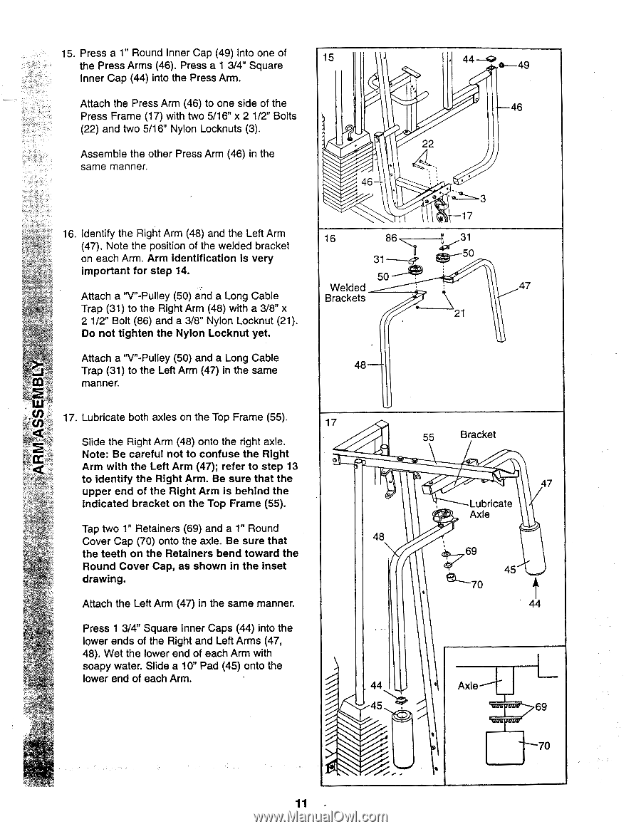
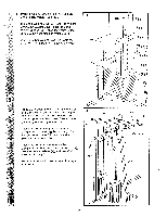
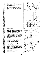
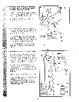
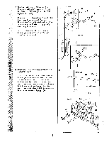
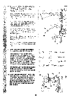
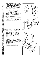
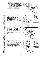
15. Press a 1" Round Inner Cap (49) into one of the Press Arms (46). Press a 1 3/4" Square Inner Cap (44) into the Press Arm. Attach the Press Arm (46) to one side of the Press Frame (17) with two 5/16" x 2 1/2" Bolts (22) and two 5/16" Nylon Locknuts (3). Assemble the other Press Arm (46) in the same manner. 16. Identify the Right Arm (48) and the Left Arm (47). Note the position of the welded bracket on each Arm. Arm identification is very important for step 14. Attach a "V"-Pulley (50) and a Long Cable Trap (31) to the Right Arm (48) with a 3/8" x 2 1/2" Bolt (86) and a 3/8" Nylon Locknut (21). Do not tighten the Nylon Locknut yet. Attach a "V"-Pulley (50) and a Long Cable Trap (31) to the Left Arm (47) in the same manner. 15 44-4> a--49 -46 22 46- 16 86 31-5P 50 Welded Brackets 3 17 47 21 48 17. Lubricate both axles on the Top Frame (55). 17 Slide the Right Arm (48) onto the right axle. Note: Be careful not to confuse the Right Arm with the Left Arm (47); refer to step 13 to identify the Right Arm. Be sure that the upper end of the Right Arm is behind the indicated bracket on the Top Frame (55). Tap two 1" Retainers (69) and a 1" Round Cover Cap (70) onto the axle. Be sure that 48 the teeth on the Retainers bend toward the Round Cover Cap, as shown in the inset drawing. Attach the Left Arm (47) in the same manner. Press 1 3/4" Square Inner Caps (44) into the lower ends of the Right and Left Arms (47, 48). Wet the lower end of each Arm with soapy water. Slide a 10" Pad (45) onto the lower end of each Arm. 44 -/--- 45 55 Bracket 47 Lubricate Axle c' .69 45 44 Axle 69 70 11 -
-
 1
1 -
2
-
3
-
4
-
5
-
 6
6 -
 7
7 -
 8
8 -
 9
9 -
 10
10 -
 11
11 -
 12
12 -
 13
13 -
 14
14 -
 15
15 -
 16
16 -
17
-
18
-
19
-
20
-
21
-
22
-
23
-
24
-
25
-
26
-
27
-
28
-
29
-
30
-
31
-
32
-
33
-
34
-
35
-
36
-
37
-
38
-
39
-
40
 |
 |