Weider Pro 9655 English Manual - Page 12
Plastic
 |
View all Weider Pro 9655 manuals
Add to My Manuals
Save this manual to your list of manuals |
Page 12 highlights
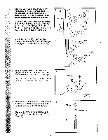
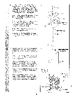
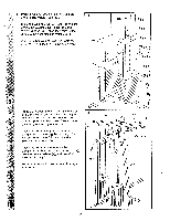
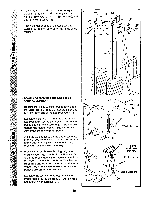
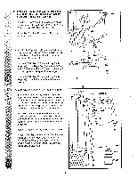
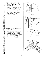
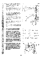
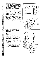
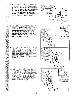
18. See the inset drawing. Attach the Military Press Arm (84) to the Pivot Arm (101) with 18 two 5/16" x 2 1/4" Bolts (33) and two 5/16" Nylon Locknuts (3). O Press two 1 1/2" Square Inner Caps (32) into the Military Press Arm (84). Press two 1" Round Inner Caps (49) into the Military Press Arm. Slide two 5" Plastic Handgrips (83) onto 21 ° the Military Press Arm. 101 Attach the Pivot Arm (101) to the Assist 67 Upright (74) with a 3/8" x 3 1/4" Bolt (67) and a 3/8" Nylon Locknut (21). 74 32 49 32 a 84 83 56 (til, 19. Press two 1" x 2" Inner Caps (107) into the Assist Arm (105). 19 Attach the Assist Arm (105) to the Leg Press Upright (56) with a 3/8" x 6" Bolt (106), two 3/8" Flat Washers (9), and a 3/8" Nylon Locknut (21). See the inset drawing. The Assist Arm must be attached to the lowest hole in the Leg Press Upright (56). The Assist Arm must also be below the welded bracket on the Assist Upright (74). 33 101 84 3 Bracket 105 56 . . . 74 Lowest Hole 56 74 106 107 9 9 105 NNN.. .... 21 12
-
 1
1 -
2
-
3
-
4
-
5
-
6
-
 7
7 -
 8
8 -
 9
9 -
 10
10 -
 11
11 -
 12
12 -
 13
13 -
 14
14 -
 15
15 -
 16
16 -
 17
17 -
18
-
19
-
20
-
21
-
22
-
23
-
24
-
25
-
26
-
27
-
28
-
29
-
30
-
31
-
32
-
33
-
34
-
35
-
36
-
37
-
38
-
39
-
40
 |
 |
