Weider Pro 9655 English Manual - Page 16
Locknut
 |
View all Weider Pro 9655 manuals
Add to My Manuals
Save this manual to your list of manuals |
Page 16 highlights
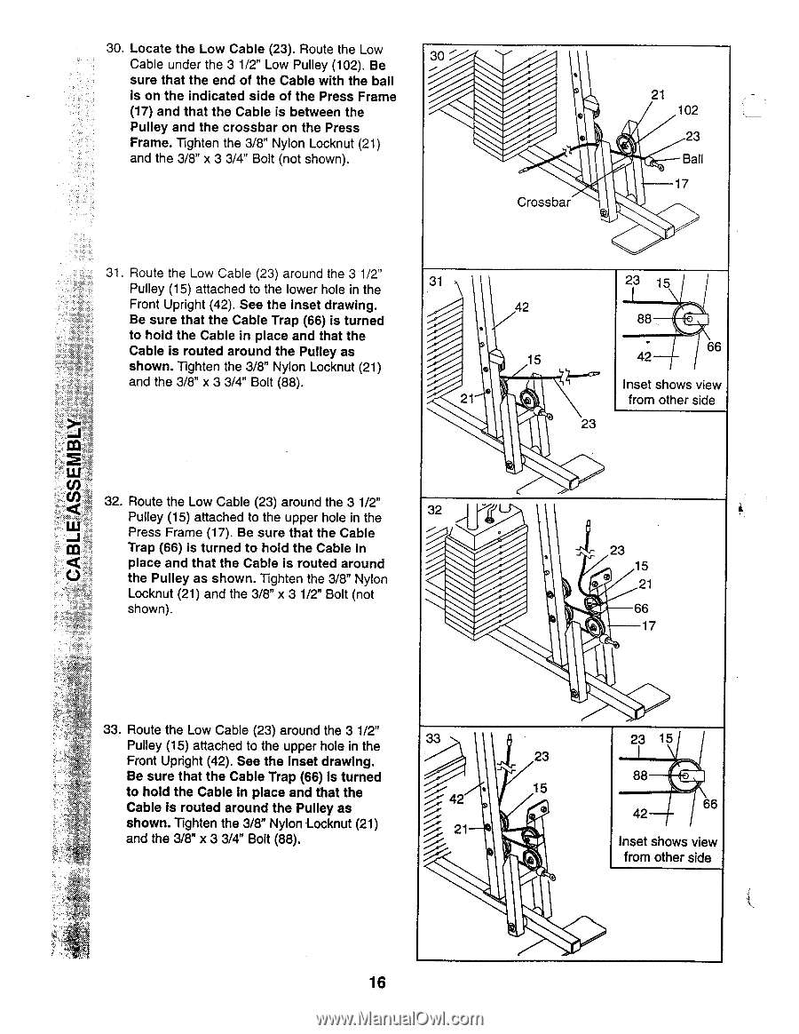
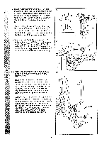
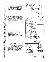
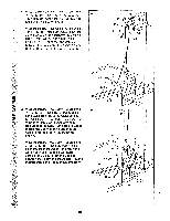
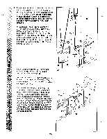
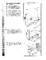
30. Locate the Low Cable (23). Route the Low Cable under the 3 1/2" Low Pulley (102). Be sure that the end of the Cable with the ball is on the indicated side of the Press Frame (17) and that the Cable is between the Pulley and the crossbar on the Press Frame. Tighten the 3/8" Nylon Locknut (21) and the 3/8" x 3 3/4" Bolt (not shown). 30 -;--- • 0 Crossbar 21 102 23 Ball 17 31. Route the Low Cable (23) around the 3 1/2" Pulley (15) attached to the lower hole in the Front Upright (42). See the inset drawing. Be sure that the Cable Trap (66) is turned to hold the Cable in place and that the Cable is routed around the Pulley as shown. Tighten the 3/8" Nylon Locknut (21) and the 3/8" x 3 3/4" Bolt (88). 31 • 21 42 15 23 15 Z-'''' ' 23 88 66 42 Inset shows view from other side 32. Route the Low Cable (23) around the 3 1/2" Pulley (15) attached to the upper hole in the Press Frame (17). Be sure that the Cable Trap (66) is turned to hold the Cable in place and that the Cable is routed around the Pulley as shown. Tighten the 3/8" Nylon Locknut (21) and the 3/8" x 3 1/2" Bolt (not shown). 32 23 15 ® 21 66 17 33. Route the Low Cable (23) around the 3 1/2" Pulley (15) attached to the upper hole in the 33 Front Upright (42). See the inset drawing. 23 Be sure that the Cable Trap (66) is turned to hold the Cable In place and that the Cable is routed around the Pulley as 15 42 ° c• shown. Tighten the 3/8" Nylon -Locknut (21) ----,. 21 and the 3/8" x 3 3/4" Bolt (88). 23 15 88 66 42 Inset shows view from other side 16
-
 1
1 -
2
-
3
-
4
-
5
-
6
-
7
-
8
-
9
-
10
-
 11
11 -
 12
12 -
 13
13 -
 14
14 -
 15
15 -
 16
16 -
 17
17 -
 18
18 -
 19
19 -
 20
20 -
 21
21 -
22
-
23
-
24
-
25
-
26
-
27
-
28
-
29
-
30
-
31
-
32
-
33
-
34
-
35
-
36
-
37
-
38
-
39
-
40
 |
 |