Weider Xr20 English Manual - Page 10
° Pulley 15 and a Cable Trap 66.
 |
View all Weider Xr20 manuals
Add to My Manuals
Save this manual to your list of manuals |
Page 10 highlights
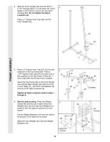
CABLE ASSEMBLY 15. Route the Long Cable (23) around a ÒVÓ- 15 Pulley (6). Using a 3/8Ó x 2 1/2Ó Bolt (7) and a 3/8Ó Nylon Locknut (21), attach the ÒVÓ-Pulley (6) and a Long Cable Trap (50) to the Right Arm (48). Be sure that the Cable is in the groove of the Pulley and that the Long Cable Trap (50) is positioned to hold the Cable in place. 23 50 7 6 21 48 16. See the inset drawing. Using a 5/16Ó x 5Ó Bolt (68) and a 5/16Ó Nylon Locknut (3), attach the Pulley Bracket (20) to the indicated bracket on the Top Frame (55). Note: The Pulley Bracket is pre-assembled with a 3 1/2Ó Pulley (15) and a Cable Trap (66). Route the Long Cable (23) around the 3 1/2Ó Pulley (15) attached to the Pulley Bracket (20). Be sure that the Cable is in the groove of the Pulley and that the Cable Trap (66) is turned to hold the Cable in place. Make sure that the 5/16Ó x 5Ó Bolt (68) is properly tightened and that the Pulley Bracket (20) can move freely. 17. Remove the 3 1/2Ó Pulley (15) from the preassembled Long ÒUÓ Bracket (57). See the inset drawing. Wrap the Long Cable (23) around the Pulley in the direction shown. Attach the Pulley (15) and a Cable Trap (66) to the indicated hole in the Long ÒUÓ Bracket (57) with a 3/8Ó x 2Ó Bolt (12) and a 3/8Ó Nylon Locknut (21). Be sure that the Cable is in the groove of the Pulley and that the Cable and Pulley move smoothly. 18. Wrap the Long Cable (23) around a 3 1/2Ó Pulley (15). Using a 3/8Ó x 1 3/4Ó Bolt (88) and a 3/8Ó Nylon Locknut (21), attach the Pulley to the indicated bracket on the Top Frame (55). Be sure that the Cable is in the groove of the Pulley and that the Cable and Pulley move smoothly. 16 68 66 20 15 23 68 55 20 3 17 23 23 15 66 12 21 57 18 23 15 Bracket 88 55 21 10
-
 1
1 -
2
-
3
-
4
-
 5
5 -
 6
6 -
 7
7 -
 8
8 -
 9
9 -
 10
10 -
 11
11 -
 12
12 -
 13
13 -
 14
14 -
 15
15 -
16
-
17
-
18
-
19
-
20
-
21
-
22
-
23
-
24
-
25
-
26
-
27
-
28
-
29
 |
 |
