Whirlpool GC5SHAXVA Installation Instructions - Page 7
Install Custom Door Panels, Install New Water Line, Connect Water Supply
 |
UPC - 883049129853
View all Whirlpool GC5SHAXVA manuals
Add to My Manuals
Save this manual to your list of manuals |
Page 7 highlights
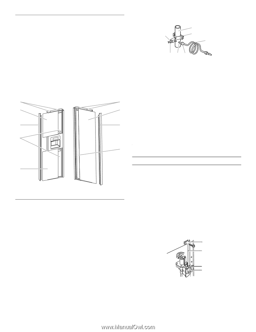
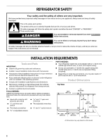
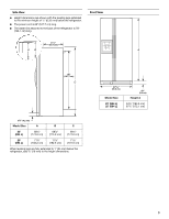
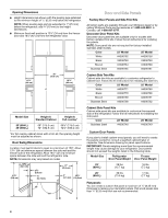
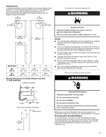
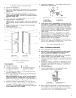
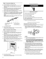
Install Custom Door Panels 1. Remove any packing tape. 2. Remove the refrigerator and freezer door trims from the hinge side of each door by pulling the trim away from the bottom of the door first. 3. Partially unscrew the two screws that hold the top trim in place. It is not necessary to completely remove the screws. Loosen the screws at least ¹⁄₄" (6.35 mm) from the trim to allow the panels to slide freely. 4. Remove the existing door panels, if panels were provided. 5. Slide custom door panels into place. NOTE: The door panels may require ¹⁄₈" (3.18 mm) cardboard fillers behind the panels to keep them from being loose in that area. 6. Replace the hinge side trims by inserting the notched end under the top trim first. 7. Tighten the two top trim screws. B B C C A A D D C A. Side trims B. Top trim screws C. Door panels D. Filler panels Install New Water Line (if required) TOOLS NEEDED: s Flat-blade screwdriver s ¹⁄₄" Drill bit s and ¹⁄₂" Open-end or two adjustable wrenches s Hand drill or electric drill (properly grounded) 1. Turn OFF main water supply. Turn ON nearest faucet long enough to clear line of water. 2. Find a ¹⁄₂" (12.70 mm) to 1¹⁄₄" (3.18 cm) vertical COLD water pipe near the refrigerator. NOTE: Horizontal pipe will work, but the following procedure must be followed: Drill on the top side of the pipe, not the bottom. This will help keep water away from the drill. This also keeps normal sediment from collecting in the valve. 3. Determine the length of copper tubing you need. Measure from the connection on the lower left rear of refrigerator to the water pipe. Add 7 ft (2.1 m) to allow for cleaning. Use ¹⁄₄" (6.35 mm) O.D. (outside diameter) copper tubing. Be sure both ends of copper tubing are cut square. 4. Using a grounded drill, drill a ¹⁄₄" (6.35 mm) hole in the cold water pipe you have selected. A G B C FE D A. Cold water pipe B. Pipe clamp C. Copper tubing D. Compression nut E. Compression sleeve F. Shutoff valve G. Packing nut 5. Fasten shutoff valve to cold water pipe with pipe clamp. Be sure outlet end is solidly in the ¹⁄₄" (6.35 mm) drilled hole in the water pipe and that washer is under the pipe clamp. Tighten packing nut. Tighten the pipe clamp screws carefully and evenly so washer makes a watertight seal. Do not overtighten or you may crush the copper tubing, especially if soft (coiled) copper tubing is used. Now you are ready to connect the copper tubing. 6. Slip compression sleeve and compression nut on copper tubing as shown in the diagram. Insert the end of the tubing into the outlet end of the shutoff valve as far as it will go. Screw the compression nut onto the outlet end with an adjustable wrench. Do not overtighten. 7. Place the free end of the tubing into a container or sink, turn ON main water supply and flush out tubing until water is clear. Turn OFF the shutoff valve on the water pipe. Connect Water Supply Style 1 - Connection to Water Valve 1. Unplug refrigerator or disconnect power. 2. Before attaching copper tubing to refrigerator, flush at least 2 qt (1.9 L) of water through the copper tubing and into a bucket to get rid of any particles in the water line. 3. Check for leaks around the saddle valve. Do not overtighten clamp or sleeve. This will crush copper tubing. 4. Attach the copper tube to the valve inlet using a compression nut and sleeve as shown. Tighten the compression nut. Do not overtighten. 5. Use the tube clamp on the back of the refrigerator to secure the tubing to the refrigerator as shown. This will help prevent damage to the tubing when the refrigerator is pushed back against the wall. 6. Turn shutoff valve ON. 7. Check for leaks. Tighten any connections (including connections at the valve) or nuts that leak. A B C D A. Tube clamp B. Copper tubing C. Compression nut D. Valve inlet 8. The ice maker is equipped with a built-in water strainer. If your water conditions require a second water strainer, install it in the ¹⁄₄" (6.35 mm) water line at either tube connection. Obtain a water strainer from your nearest appliance dealer. 7
-
 1
1 -
 2
2 -
 3
3 -
 4
4 -
 5
5 -
 6
6 -
 7
7 -
 8
8 -
 9
9 -
 10
10 -
 11
11 -
 12
12 -
13
-
14
-
15
-
16
-
17
-
18
-
19
-
20
-
21
-
22
-
23
-
24
-
25
-
26
-
27
-
28
 |
 |