Whirlpool WGD9500T Use and Care Manual - Page 9
Burner input requirements - reviews
 |
View all Whirlpool WGD9500T manuals
Add to My Manuals
Save this manual to your list of manuals |
Page 9 highlights
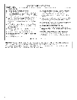
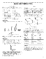
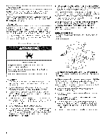
• Must include a shutoff valve: In the U.S.A.: An individual manual shutoff valve must be installed within six (6) feet (1.8 m) of the dryer in accordance with the National Fuel Gas Code, ANSI Z223.1. The location should be easy to reach for opening and closing. In Canada: An individual manual shutoff valve must be installed in accordance with the B149.1, Natural Gas and Propane Installation Code. It is recommended that an individual manual shutoff valve be installed within six (6) feet (1.8 m) of the dryer. The location should be easy to reach for opening and closing. A C E B D A. %" flexible gas connector B. %" pipe to flare adapter fitting C. Vs" NPT minimum plugged tapping D. Y2" NPT gas supply line E. Gas shutoff valve Dryer gas pipe • The gas pipe that comes out through the rear of your dryer has a %" male pipe thread. A. Y2"NPT gas supply line B. %" NPT dryer pipe *NOTE: If the dryer is mounted on a pedestal, the gas pipe height must be an additional 10" (25.4 cm) or 15.5" (39.4 cm) from the floor, depending on the pedestal model. For a garage installation, the gas pipe height must be an additional 18" (46 cm) from the floor. Gas supply connection requirements • Use an elbow and a 3/8"flare x 3/8"NPT adapter fitting between the flexible gas connector and the dryer gas pipe, as needed to avoid kinking. • Use only pipe-joint compound. Do not use TEFLON _t tape. • This dryer must be connected to the gas supply line with a listed flexible gas connector that complies with the standard for connectors for gas appliances, ANSI Z21.24 or CSA 6.10. Burner input requirements Elevations above 10,000 ft (3,048 m): • When installed above 10,000 ft (3,048 m) a 4% reduction of the burner Btu rating shown on the model/serial number plate is required for each 1,000 ft (305 m) increase in elevation. Gas supply pressure testing • The dryer must be disconnected from the gas supply piping system during pressure testing at pressures greater than 1/2psi. Fire Hazard Use a heavy metal vent. Do not use a plastic vent. Do not use a metal foil vent. Failure to follow these instructions can result in death or fire. WARNING: To reduce the risk of fire, this dryer MUST BE EXHAUSTED OUTDOORS. IMPORTANT: Observe all governing codes and ordinances. The dryer exhaust must not be connected into any gas vent, chimney, wall, ceiling or a concealed space of a building. If using an existing vent system • Clean lint from the entire length of the system and make sure exhaust hood is not plugged with lint. • Replace any plastic or metal foil vent with rigid or flexible heavy metal vent. • Review Vent system chart. Modify existing vent system if necessary to achieve the best drying performance.
-
 1
1 -
2
-
3
-
 4
4 -
 5
5 -
 6
6 -
 7
7 -
 8
8 -
 9
9 -
 10
10 -
 11
11 -
 12
12 -
 13
13 -
 14
14 -
15
-
16
-
17
-
18
-
19
-
20
-
21
-
22
-
23
-
24
-
25
-
26
-
27
-
28
-
29
-
30
-
31
-
32
-
33
-
34
-
35
-
36
-
37
-
38
-
39
-
40
-
41
-
42
-
43
-
44
-
45
-
46
-
47
-
48
-
49
-
50
-
51
-
52
 |
 |
