Yamaha EMX62M Owner's Manual - Page 2
The Owner's Manual, Revisions, Révisions du Mode, d'emploi de l'EMX62M, MAIN
 |
View all Yamaha EMX62M manuals
Add to My Manuals
Save this manual to your list of manuals |
Page 2 highlights
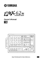
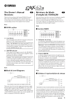
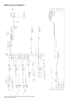
The Owner's Manual E Revisions Thank you for purchasing the Yamaha EMX62M Powered Mixer. Parts of the EMX62M owner's manual have been revised. Please refer to the following revisions rather than the corresponding sections of the original owner's manual. P.11 ■ MAIN section D C C Level Meter This LED display shows the level of signals received at the MAIN OUT jack (input/output panel 9). Note: The SPEAKERS 1 & 2 jacks (rear panel 1) output the signals received at the MAIN OUT jack via the internal power amplifier. Check the output signal level via the LIMITER indicator (D). D LIMITER indicator If the output level of signals received at the SPEAKERS 1 & 2 jacks (the output of internal power amplifier) reaches maximum, the indicator will light. Caution: If the LIMITER indicator flashes continuously, the internal power amplifier section is being excessively overloaded and may malfunction. Reduce the output level at the MASTER control (B) below the level that the indicator flashes only briefly on the highest transient peaks. P.21 ■ Block & Level Diagrams PA +11dB +4dB SPEAKERS OUT MAXIMUM OUTPUT POWER [200W/4Ω] NOMINAL OUTPUT [40W/4Ω] +30dB +20dB +10dB 0dB Power Amplifier output section level diagram (bottom right) These plots show the nominal output and maximum output levels of signals received at the SPEAKERS 1 & 2 jacks. If the output level is +4dB (Level Meter "0"), the internal power amplifier will deliver 40W into a 4Ω load. If the output level is +11dB (LIMITER indicator lights), the internal amplifier will deliver a maximum of 200W into a 4Ω load. Révisions du Mode F d'emploi de l'EMX62M Nous vous remercions d'avoir opté pour le mélangeur amplifié EMX62M de Yamaha. Nous avons apporté une série de révisions au Mode d'emploi de l'EMX62M. Nous vous invitons à tenir compte de ces changements dans les sections correspondantes du Mode d'emploi original. P.10 ■ Section MAIN D C C Indicateur de niveau Cet indicateur à diodes affiche le niveau des signaux reçus par la borne MAIN OUT (tableau des entrées/sorties 9). Remarque: Les bornes SPEAKERS 1 & 2 (face arrière 1) produisent les signaux transmis à la borne MAIN OUT et amplifiés par l'amplificateur de puissance interne. Le témoin LIMITER (D) permet de contrôler le niveau du signal de sortie. D Témoin LIMITER Ce témoin s'allume lorsque le niveau du signal reçu aux bornes SPEAKERS 1 & 2 (et transmis par l'amplificateur de puissance) atteint la valeur maximale. Attention: Si le témoin LIMITER clignote de façon permanente, l'amplificateur de puissance interne est saturé et pourrait présenter un dysfonctionnement. Dans ce cas, réduisez le niveau de sortie avec la commande Master (B), de sorte que le témoin ne clignote plus que brièvement aux pics de niveau. P.21 ■ Schéma et représentation de niveau PA +11dB +4dB SPEAKERS OUT MAXIMUM OUTPUT POWER [200W/4Ω] NOMINAL OUTPUT [40W/4Ω] +30dB +20dB +10dB 0dB Représentation de niveau de la section amplificateur de puissance (en bas à droite) Ces tracés indiquent le niveau de sortie nominal et le niveau de sortie maximum des signaux reçus aux bornes SPEAKERS 1 & 2. Avec un niveau de sortie de +4dB (indicateur de niveau "0"), l'amplificateur de puissance interne produit 40W maximum sous 4Ω. Avec un niveau de sortie de +11dB (témoin LIMITER allumé), l'amplificateur de puissance interne produit 200W maximum sous 4Ω. 1 EMX62M
-
 1
1 -
 2
2 -
 3
3 -
 4
4 -
 5
5 -
 6
6 -
 7
7 -
 8
8 -
9
-
10
-
11
-
12
-
13
-
14
-
15
-
16
-
17
-
18
-
19
-
20
-
21
-
22
-
23
-
24
-
25
-
26
 |
 |