Yamaha MT2X Owner's Manual - Page 6
The Controls And Their Functions - recorder
 |
View all Yamaha MT2X manuals
Add to My Manuals
Save this manual to your list of manuals |
Page 6 highlights
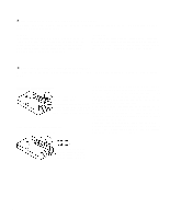
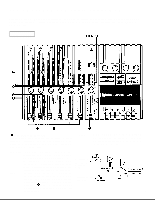
THE CONTROLS AND THEIR FUNCTIONS This section explains the names and functions of all the knobs, sliders, and switches for the mixer, recorder, meter/ monitor, and connector sections. Familiarize yourself with them in order to take full advantage of the MT2X's versatile functions. MIXER SECTION INPUT SELECTOR SWITCHES These three-position switches are provided on input channels 1 through 4. Position them according to the operation to be performed. Note that input channels 5 and 6 only accept line input. TAPE: Set the switch to this position to playback material which has already been recorded on this channel. Channels 1-4 correspond to tracks 1-4 on the tape. MIC/LINE: Only input channels 1 and 2 accept microphone input. This position on the chan- nel 3 and 4 inputs is simply marked "LINE". Set this switch to the proper position when the output of a microphone, keyboard instrument, or electric guitar is connected to the Microphone or instrument to channel 1 or 2 corresponding input jack on the front panel. OFF: Be sure to set the switch to this position when the channel is not being used, or when you don't want to playback material already recorded on the track. Although sliding the Sounds already recorded input fader to the "O" position will stop the signal, it's a good idea to also set the switch to OFF. 4
-
 1
1 -
 2
2 -
 3
3 -
 4
4 -
 5
5 -
 6
6 -
 7
7 -
 8
8 -
 9
9 -
 10
10 -
 11
11 -
 12
12 -
13
-
14
-
15
-
16
-
17
-
18
-
19
-
20
-
21
-
22
-
23
-
24
-
25
-
26
-
27
-
28
-
29
-
30
-
31
-
32
-
33
-
34
-
35
-
36
-
37
-
38
-
39
-
40
-
41
-
42
 |
 |
