2009 Kawasaki Vulcan 2000 Classic LT Owners Manual - Page 52
2009 Kawasaki Vulcan 2000 Classic LT Manual

Page 52 highlights
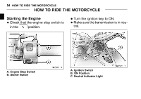
50 GENERAL INFORMATION Electric Accessory Connectors The electric power of the battery can be used through the electric accessory connectors regardless of ignition switch position. Observe and follow the notes listed below. Electric Accessory Connectors Location Polarity Wire Color (+) White/Blue Under Rider's Seat (-) Black/Yellow Under Fuel Tank Maximum Current : (+) (-) White/Blue Black/Yellow 10 A using the electric accessory • When connectors under the fuel tank, the electric accessory connection to the connectors should be done by an authorized Kawasaki dealer. A. Electric Accessory Connectors
-
 1
1 -
2
-
3
-
4
-
5
-
6
-
7
-
8
-
9
-
10
-
11
-
12
-
13
-
14
-
15
-
16
-
17
-
18
-
19
-
20
-
21
-
22
-
23
-
24
-
25
-
26
-
27
-
28
-
29
-
30
-
31
-
32
-
33
-
34
-
35
-
36
-
37
-
38
-
39
-
40
-
41
-
42
-
43
-
44
-
45
-
46
-
 47
47 -
 48
48 -
 49
49 -
 50
50 -
 51
51 -
 52
52 -
 53
53 -
 54
54 -
 55
55 -
 56
56 -
 57
57 -
58
-
59
-
60
-
61
-
62
-
63
-
64
-
65
-
66
-
67
-
68
-
69
-
70
-
71
-
72
-
73
-
74
-
75
-
76
-
77
-
78
-
79
-
80
-
81
-
82
-
83
-
84
-
85
-
86
-
87
-
88
-
89
-
90
-
91
-
92
-
93
-
94
-
95
-
96
-
97
-
98
-
99
-
100
-
101
-
102
-
103
-
104
-
105
-
106
-
107
-
108
-
109
-
110
-
111
-
112
-
113
-
114
-
115
-
116
-
117
-
118
-
119
-
120
-
121
-
122
-
123
-
124
-
125
-
126
-
127
-
128
-
129
-
130
-
131
-
132
-
133
-
134
-
135
-
136
-
137
-
138
-
139
-
140
-
141
-
142
-
143
-
144
-
145
-
146
-
147
-
148
-
149
-
150
-
151
-
152
-
153
-
154
-
155
-
156
-
157
-
158
-
159
-
160
-
161
-
162
-
163
-
164
-
165
-
166
-
167
-
168
-
169
-
170
-
171
-
172
-
173
-
174
 |
 |

50
GENERAL INFORMATION
Electric Accessory Connectors
The electric power of the battery can
be used through the electric acces-
sory connectors regardless of ignition
switch position.
Observe and follow
the notes listed below.
Electric Accessory Connectors
Location
Polarity
Wire Color
(+)
White/Blue
Under Rider’s
Seat
(–)
Black/Yellow
(+)
White/Blue
Under Fuel
Tank
(–)
Black/Yellow
Maximum Current :
10 A
•
When using the electric accessory
connectors under the fuel tank, the
electric accessory connection to the
connectors should be done by an au-
thorized Kawasaki dealer.
A. Electric Accessory Connectors