2011 Kawasaki Mule 610 4x4 XC Owners Manual - Page 5
2011 Kawasaki Mule 610 4x4 XC Manual

Page 5 highlights
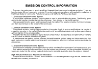
EMISSION CONTROL INFORMATION To protect the environment in which we all live, Kawasaki has incorporated crankcase emission (1) and exhaust emission (2) and evaporative emission (3) control systems in compliance with applicable regulations of the United States Environmental Protections Agency and California Air Resources Board. 1. Crankcase Emission Control System A sealed-type crankcase emission control system is used to eliminate blow-by gases. The blow-by gases are led to the breather chamber through the crankcase. Then, it is led to the intake manifold. Oil is separated from the gases while passing through the inside of the breather chamber from the crankcase, and then returned back to the bottom of the crankcase. 2. Exhaust Emission Control System The exhaust emission control system applied to this engine family is engine modifications that consist of a catalytic converter in the muffler (California model only), a modified carburetor and ignition system having optimum ignition timing characteristics. The carburetor has been calibrated to provide lean air/fuel mixture characteristics and optimum fuel economy with a suitable air cleaner and exhaust system. A maintenance free ignition system provides the most favorable ignition timing and helps maintain a thorough combustion process within the engine which contributes to a reduction of exhaust pollutants entering the atmosphere. 3. Evaporative Emission Control System The evaporative emission control system for this vehicle consists of low permeation fuel hoses and fuel tank. Also, vapors caused by fuel evaporation in the fuel system are not vented into the atmosphere. Instead, fuel vapors are routed into the running engine to be burned, or stored in a canister when the engine is stopped. High Altitude Performance Adjustment Information To improve the EMISSION CONTROL PERFORMANCE of vehicles operated at high altitude, Kawasaki recommends the following modification.
-
 1
1 -
 2
2 -
 3
3 -
 4
4 -
 5
5 -
 6
6 -
 7
7 -
 8
8 -
 9
9 -
 10
10 -
 11
11 -
12
-
13
-
14
-
15
-
16
-
17
-
18
-
19
-
20
-
21
-
22
-
23
-
24
-
25
-
26
-
27
-
28
-
29
-
30
-
31
-
32
-
33
-
34
-
35
-
36
-
37
-
38
-
39
-
40
-
41
-
42
-
43
-
44
-
45
-
46
-
47
-
48
-
49
-
50
-
51
-
52
-
53
-
54
-
55
-
56
-
57
-
58
-
59
-
60
-
61
-
62
-
63
-
64
-
65
-
66
-
67
-
68
-
69
-
70
-
71
-
72
-
73
-
74
-
75
-
76
-
77
-
78
-
79
-
80
-
81
-
82
-
83
-
84
-
85
-
86
-
87
-
88
-
89
-
90
-
91
-
92
-
93
-
94
-
95
-
96
-
97
-
98
-
99
-
100
-
101
-
102
-
103
-
104
-
105
-
106
-
107
-
108
-
109
-
110
-
111
-
112
-
113
-
114
-
115
-
116
-
117
-
118
-
119
-
120
-
121
-
122
-
123
-
124
-
125
-
126
-
127
-
128
-
129
-
130
-
131
-
132
-
133
-
134
-
135
-
136
-
137
-
138
-
139
 |
 |
