2011 Mercedes SL-Class Owner's Manual - Page 228
2011 Mercedes SL-Class Manual
Page 228 highlights
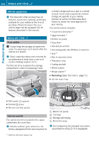
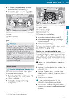
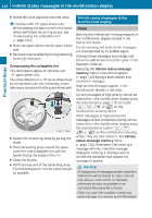
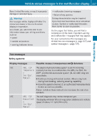
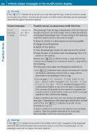
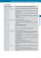
226 X Vehicle status messages in the multifunction display Screw the valve cap back onto the valve. i Vehicles with 19" spare wheel only: Before placing the spare wheel in the spare wheel well fasten tensioning straps, see "Compressing the collapsible tire" (Y page 226). X Place the spare wheel into the spare wheel well. X Secure the spare wheel by turning retaining screw = clockwise. Vehicle status messages in the multifunction display Notes Warning and malfunction messages appear in the multifunction display located in the instrument cluster. Certain warning and malfunction messages are accompanied by an audible signal. Address these messages accordingly and follow the additional instructions given in this Operator's Manual. Selecting the Vehicle status message memory menu in the control system (Y page 120) displays both cleared and uncleared messages. High-priority messages appear in the multifunction display in red color. Certain messages of high priority cannot be cleared from the multifunction display using the reset button (Y page 112) or button &, *, U or V on the multifunction steering wheel. Other messages of high priority and messages of less immediate priority can be cleared from the multifunction display using the reset button or button &, *, U or V on the multifunction steering wheel. They are then stored in the Vehicle status message memory menu (Y page 120). Remember that clearing a message will only make the message disappear. Clearing a message will not correct the condition that caused the message to appear. Practical hints Compressing the collapsible tire This description applies to vehicles with 19" spare wheel only. The collapsible tire on a 19" spare wheel must be compressed with two tensioning straps before you can store it in the spare wheel well. X Extend the tensioning strap by pulling the slider. X Place tensioning strap around the spare wheel rim and collapsible tire with the buckle facing the inside of the rim. X Close the buckle. X Pull the loose end of the tensioning strap. The tensioning strap must be pulled as tight as possible. G Warning! All categories of messages contain important information which should be taken note of and, where a malfunction is indicated, addressed as soon as possible at an authorized Mercedes-Benz Center. Failure to repair the condition noted may cause damage not covered by the Mercedes-
-
 1
1 -
2
-
3
-
4
-
5
-
6
-
7
-
8
-
9
-
10
-
11
-
12
-
13
-
14
-
15
-
16
-
17
-
18
-
19
-
20
-
21
-
22
-
23
-
24
-
25
-
26
-
27
-
28
-
29
-
30
-
31
-
32
-
33
-
34
-
35
-
36
-
37
-
38
-
39
-
40
-
41
-
42
-
43
-
44
-
45
-
46
-
47
-
48
-
49
-
50
-
51
-
52
-
53
-
54
-
55
-
56
-
57
-
58
-
59
-
60
-
61
-
62
-
63
-
64
-
65
-
66
-
67
-
68
-
69
-
70
-
71
-
72
-
73
-
74
-
75
-
76
-
77
-
78
-
79
-
80
-
81
-
82
-
83
-
84
-
85
-
86
-
87
-
88
-
89
-
90
-
91
-
92
-
93
-
94
-
95
-
96
-
97
-
98
-
99
-
100
-
101
-
102
-
103
-
104
-
105
-
106
-
107
-
108
-
109
-
110
-
111
-
112
-
113
-
114
-
115
-
116
-
117
-
118
-
119
-
120
-
121
-
122
-
123
-
124
-
125
-
126
-
127
-
128
-
129
-
130
-
131
-
132
-
133
-
134
-
135
-
136
-
137
-
138
-
139
-
140
-
141
-
142
-
143
-
144
-
145
-
146
-
147
-
148
-
149
-
150
-
151
-
152
-
153
-
154
-
155
-
156
-
157
-
158
-
159
-
160
-
161
-
162
-
163
-
164
-
165
-
166
-
167
-
168
-
169
-
170
-
171
-
172
-
173
-
174
-
175
-
176
-
177
-
178
-
179
-
180
-
181
-
182
-
183
-
184
-
185
-
186
-
187
-
188
-
189
-
190
-
191
-
192
-
193
-
194
-
195
-
196
-
197
-
198
-
199
-
200
-
201
-
202
-
203
-
204
-
205
-
206
-
207
-
208
-
209
-
210
-
211
-
212
-
213
-
214
-
215
-
216
-
217
-
218
-
219
-
220
-
221
-
222
-
 223
223 -
 224
224 -
 225
225 -
 226
226 -
 227
227 -
 228
228 -
 229
229 -
 230
230 -
 231
231 -
 232
232 -
 233
233 -
234
-
235
-
236
-
237
-
238
-
239
-
240
-
241
-
242
-
243
-
244
-
245
-
246
-
247
-
248
-
249
-
250
-
251
-
252
-
253
-
254
-
255
-
256
-
257
-
258
-
259
-
260
-
261
-
262
-
263
-
264
-
265
-
266
-
267
-
268
-
269
-
270
-
271
-
272
-
273
-
274
-
275
-
276
-
277
-
278
-
279
-
280
-
281
-
282
-
283
-
284
-
285
-
286
-
287
-
288
-
289
-
290
-
291
-
292
-
293
-
294
-
295
-
296
-
297
-
298
-
299
-
300
-
301
-
302
-
303
-
304
-
305
-
306
-
307
-
308
-
309
-
310
-
311
-
312
-
313
-
314
-
315
-
316
 |
 |
