3M X55I Operation Guide - Page 5
About Restart switch - s55i
 |
View all 3M X55I manuals
Add to My Manuals
Save this manual to your list of manuals |
Page 5 highlights
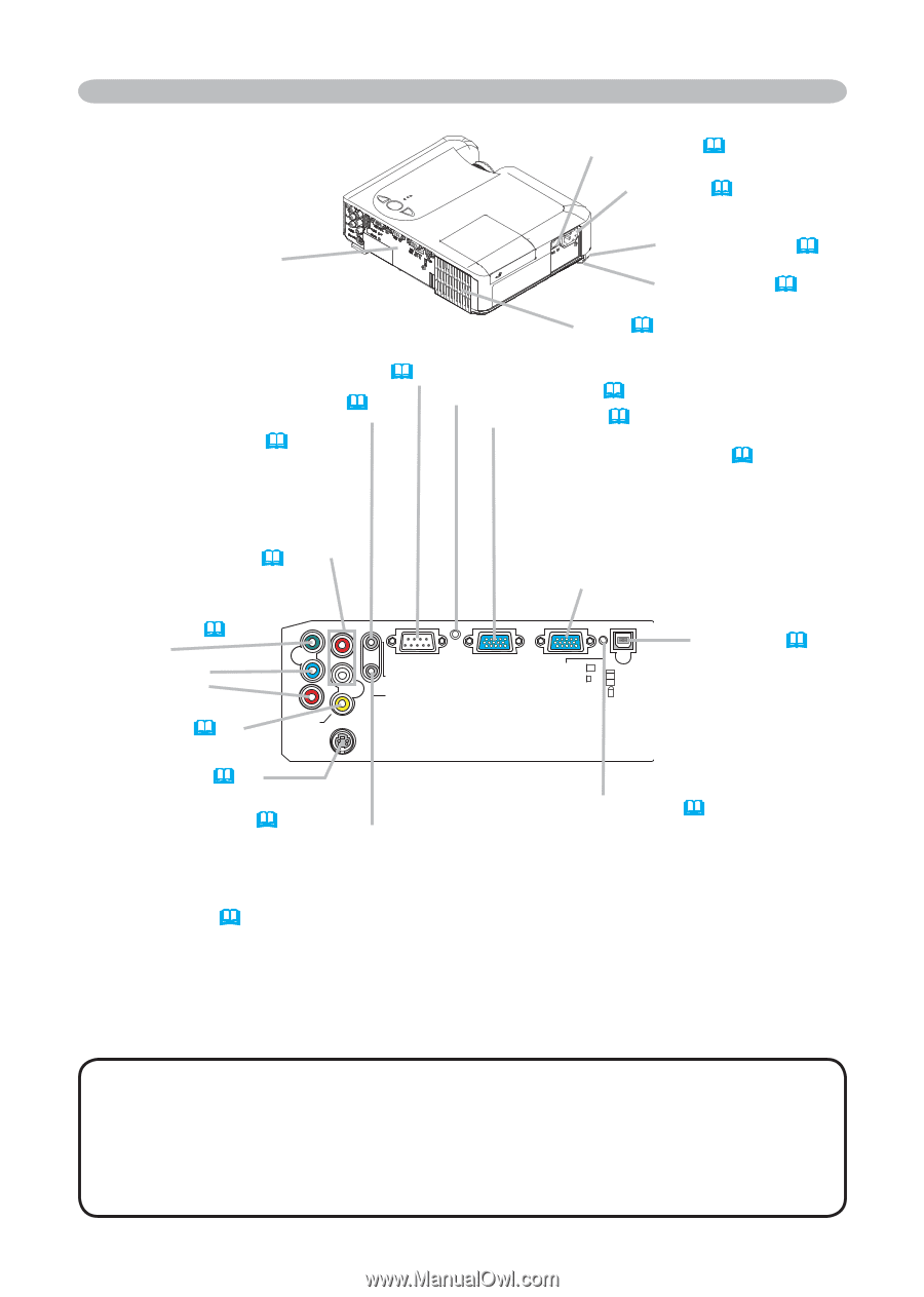
3M™ Digital Projector S55i/X55i Part names Power switch (17) AC inlet (14) Ports (See below.) Rear-Left side Elevator button (9) Elevator foot (9) Vent (7) CONTROL port (12) AUDIO-OUT port (12) Restart switch (*) (48) RGB IN1 port (12) AUDIO IN2 L/R port (13) (In the default setting, the AUDIO IN2 L/R port is the audio port for the VIDEO, S-VIDEO and COMPONENT VIDEO ports, however it is possible to change the settings. 34) COMPONENT VIDEO ports (13) Y CB/PB CR/PR Y CB/PB CR/PR AUDIO IN2 R L CONTROL AUDIO OUT AUDIO IN1 RGB IN2 /RGB OUT port (12) (Use the RGB IN OUT switch to select RGB IN2 or RGB OUT for this port.) RGB IN2 port: Inputs the RGB signal from a PC. RGB OUT port: When connected to a monitor, outputs the signal input via RGB IN1. RGB IN1 RGB IN2 RGB OUT USB K USB port (12) VIDEO port (13) VIDEO S-VIDEO S-VIDEO port (13) AUDIO IN1 port (12) (In the default setting, the AUDIO IN1 port is the audio port for the RGB IN1 and RGB IN2 ports, however, it is possible to change the settings. 34) Ports RGB IN OUT switch (12) Use this button to select either RGB IN2 or RGB OUT for the corresponding port. When this switch is not pushed in, RGB IN2 is selected. When this switch is pushed in, RGB OUT is selected. NOTE (*) About Restart switch: This projector is controlled by an internal microprocessor. Under certain exceptional circumstances, the projector may not operate correctly and the microprocessor will need to be reset. In such a case, please push the Restart switch by using a cocktail stick or similar, and before turning on again, make the projector cool down at least 10 minutes without operating. Only push the Restart switch in these exceptional instances. © 3M 2005. All Rights Reserved. 5
-
 1
1 -
 2
2 -
 3
3 -
 4
4 -
 5
5 -
 6
6 -
 7
7 -
 8
8 -
 9
9 -
 10
10 -
 11
11 -
12
-
13
-
14
-
15
-
16
-
17
-
18
-
19
-
20
-
21
-
22
-
23
-
24
-
25
-
26
-
27
-
28
-
29
-
30
-
31
-
32
-
33
-
34
-
35
-
36
-
37
-
38
-
39
-
40
-
41
-
42
-
43
-
44
-
45
-
46
-
47
-
48
-
49
-
50
-
51
-
52
-
53
-
54
 |
 |