ASRock ALiveDual-eSATA2 User Manual
ASRock ALiveDual-eSATA2 Manual
 |
View all ASRock ALiveDual-eSATA2 manuals
Add to My Manuals
Save this manual to your list of manuals |
ASRock ALiveDual-eSATA2 manual content summary:
- ASRock ALiveDual-eSATA2 | User Manual - Page 1
ALiveDual-eSATA2 User Manual Version 1.2 Published February 2008 Copyright©2008 ASRock INC. All rights reserved. 1 - ASRock ALiveDual-eSATA2 | User Manual - Page 2
without written consent of ASRock Inc. Products and corporate names appearing in this manual may or may not be manual. With respect to the contents of this manual, ASRock does not provide warranty of any kind, either expressed ONLY The Lithium battery adopted on this motherboard contains Perchlorate, - ASRock ALiveDual-eSATA2 | User Manual - Page 3
1.2 Specifications 6 1.3 Motherboard Layout 10 1.4 ASRock 8CH_eSATAII I/O Plus 11 2 . Installation 12 Pre-installation Precautions 12 2.1 CPU Installation 13 2.2 Installation of CPU Fan and Heatsink 13 2.3 Installation of Memory Modules (DIMM 14 2.4 Expansion Slots (PCI, PCI Express and AGP - ASRock ALiveDual-eSATA2 | User Manual - Page 4
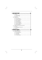
38 3.1.1 BIOS Menu Bar 38 3.1.2 Navigation Keys 39 3.2 Main Screen 39 3.3 Advanced Screen 40 3.3.1 CPU Configuration 40 Screen 54 4 . Software Support 55 4.1 Install Operating System 55 4.2 Support CD Information 55 4.2.1 Running Support CD 55 4.2.2 Drivers Menu 55 4.2.3 Utilities - ASRock ALiveDual-eSATA2 | User Manual - Page 5
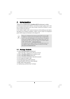
the BIOS software might be updated, the content of this manual will be subject to change without notice. In case any modifications of this manual occur, the updated version will be available on ASRock website without further notice. You may find the latest VGA cards and CPU support lists on ASRock - ASRock ALiveDual-eSATA2 | User Manual - Page 6
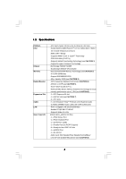
- Support DDRII800/667/533 - Max. capacity: 8GB (see CAUTION 3) - CPU Frequency Stepless Control (see CAUTION 4) - ASRock U-COP (see CAUTION 5) - Boot Failure Guard (B.F.G.) - ASRock AM2 Boost: ASRock Patented Technology to boost memory performance up to 12.5% (see CAUTION 6) - 1 x PCI Express x16 - ASRock ALiveDual-eSATA2 | User Manual - Page 7
Connector BIOS Feature Support CD Hardware Monitor OS Certifications - 2 x Serial ATA 1.5Gb/s connectors by NVIDIA® nForce3 250, support RAID (RAID 0, RAID 1 and JBOD) and "Hot Plug" functions - 2 x Serial ATAII 3.0Gb/s connectors by JMicron® JMB363 (PCIE x1 interface), support RAID (RAID 0, RAID 1 - ASRock ALiveDual-eSATA2 | User Manual - Page 8
. To improve heat dissipation, remember to spray thermal grease between the CPU and the heatsink when you install the PC system. 6. This motherboard supports ASRock AM2 Boost overclocking technology. If you enable this function in the BIOS setup, the memory performance will improve up to 12.5%, but - ASRock ALiveDual-eSATA2 | User Manual - Page 9
Guide" on page 27 to adjust your SATAII hard disk drive to SATAII mode. You can also connect SATA hard disk to SATAII connector directly. 10. This motherboard supports Windows® VistaTM 64-bit / VistaTM / XP 64-bit / XP SP1 or SP2 / 2000 SP4. 12. WiFi header supports WiFi+AP function with ASRock WiFi - ASRock ALiveDual-eSATA2 | User Manual - Page 10
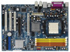
4Mb BIOS CD1 AUDIO CODEC 1 HDMI_SPDIF1 WIFI 1 AUDIO1 1 JR1 JL1 NVIDIA M1695 Chipset PCI EXPRESS SATA2 SATA1 JMicron JMB363 DDRII800 PCIE1 SATA FSB1GHz ALiveDual-eSATA2 RAID AGP1 AGP 8X NVIDIA nForce3 250 Chipset PCI1 eSATAII PCI2 RoHS PCI3 FLOPPY1 CLRCMOS1 1 IDE1 CMOS BATTERY USB2 - ASRock ALiveDual-eSATA2 | User Manual - Page 11
1 . 4 ASRock 8CH_eSATAII I/O Plus 1 2 3 4 7 5 8 6 9 14 13 12 11 10 1 PS/2 Mouse Port (Green) 2 Parallel Port 3 RJ-45 Port 4 Side Speaker (Gray) 5 Rear Speaker (Black) 6 Central / Bass (Orange) 7 - ASRock ALiveDual-eSATA2 | User Manual - Page 12
, peripherals, and/or components. 1. Unplug the power cord from the wall socket before touching any component. 2. To avoid damaging the motherboard components due to static electricity, NEVER place your motherboard directly on the carpet or the like. Also remember to use a grounded wrist strap - ASRock ALiveDual-eSATA2 | User Manual - Page 13
. Make sure that the CPU and the heatsink are securely fastened and in good contact with each other. Then connect the CPU fan to the CPU FAN connector (CPU_FAN1, see Page 10, No. 6). For proper installation, please kindly refer to the instruction manuals of the CPU fan and the heatsink. 13 - ASRock ALiveDual-eSATA2 | User Manual - Page 14
2.3 Installation of Memory Modules (DIMM) This motherboard provides four 240-pin DDRII (Double Data Rate II) DIMM slots, and supports Dual Channel Memory Technology. For dual channel configuration, you always need to install identical (the same brand, speed, size and chiptype) DDRII DIMM pair in - ASRock ALiveDual-eSATA2 | User Manual - Page 15
matches the break on the slot. notch break notch break The DIMM only fits in one correct orientation. It will cause permanent damage to the motherboard and the DIMM if you force the DIMM into the slot at incorrect orientation. Step 3. Firmly insert the DIMM into the slot until the retaining - ASRock ALiveDual-eSATA2 | User Manual - Page 16
on ALiveDual-eSATA2 motherboard. PCI Slots: PCI slots are used to install expansion cards that have the 32-bit PCI interface. PCIE Slot: PCIE1 (PCIE x16 slot) is used for PCI Express cards with x16 lane width graphics cards. AGP Slot: The AGP slot is used to install a graphics card. The ASRock AGP - ASRock ALiveDual-eSATA2 | User Manual - Page 17
short pin2 and pin3 on CLRCMOS1 for 5 seconds. However, please do not clear the CMOS right after you update the BIOS. If you need to clear the CMOS when you just finish updating the BIOS, you must boot up the system first, and then shut it down before you do the clearCMOS action. 17 - ASRock ALiveDual-eSATA2 | User Manual - Page 18
IDE device on this motherboard, please set the IDE device as "Master". Please refer to the instruction of your IDE device vendor SATA2 SATA1 These two Serial ATA (SATA) connectors are supported by NVIDIA® nForce3 250 southbridge, support SATA data cables for internal storage devices. The current - ASRock ALiveDual-eSATA2 | User Manual - Page 19
cable can be connected to the SATA / SATAII hard disk or the SATAII connector on this motherboard. You can also use the SATA data cable to connect SATAII_2 connector and eSATAII connector. panel, there is one USB 2.0 header on this motherboard. This USB 2.0 header can support two USB 2.0 ports. 19 - ASRock ALiveDual-eSATA2 | User Manual - Page 20
GND GND CD-R IRTX +5VSB DUMMY 1 GND IRRX CD1 This header supports WiFi+AP function with ASRock WiFi-802.11g or WiFi-802.11n module, an easy-to-use wireless supports an optional wireless transmitting and receiving infrared module. This connector allows you to receive stereo audio input from sound - ASRock ALiveDual-eSATA2 | User Manual - Page 21
3 +12V CPU_FAN_SPEED cable to this connector and 4 FAN_SPEED_CONTROL match the black wire to the ground pin. Though this motherboard provides 4-Pin CPU fan (Quiet Fan) support, the 3-Pin CPU fan still can work successfully even without the fan speed control function. If you plan to connect the - ASRock ALiveDual-eSATA2 | User Manual - Page 22
HDMI_SPDIF Cable (Optional) C B A Please connect the black end (A) of HDMI_SPDIF cable to the HDMI_SPDIF header on the motherboard. Then connect the white end (B or C) of HDMI_SPDIF cable to the HDMI_SPDIF connector of HDMI VGA card. A. black end B. white end (2-pin) C. white end (3-pin) + - ASRock ALiveDual-eSATA2 | User Manual - Page 23
card may be damaged. For example, this picture shows the wrong example of connecting HDMI_SPDIF cable to the fan connector of PCI Express VGA card. Please refer to the VGA card user manual for connector usage in advance. Connect the HDMI output connector on HDMI VGA card to HDMI device, such as HDTV - ASRock ALiveDual-eSATA2 | User Manual - Page 24
Interface Introduction What is eSATAII? This motherboard supports eSATAII interface, the external SATAII specification. 2. If you set "PCIE-SATAII Operation Mode" option in BIOS setup to IDE mode, Hot Plug function is not supported with eSATAII devices. If you still want to use eSATAII function - ASRock ALiveDual-eSATA2 | User Manual - Page 25
How to install eSATAII? SATAII_2 eSATAII_TOP 1. In order to enable the eSATAII port of the I/O shield, you need to connect the orange SATAII connector (SATAII_2; see p.10 No.10) and the eSATAII connector (eSATAII_TOP; see p.10 No.34) with a SATA data cable first. Connect the SATA data cable to - ASRock ALiveDual-eSATA2 | User Manual - Page 26
Comparison between eSATAII and other devices IEEE 1394 USB 2.0 SATA eSATAII/SATAII 400Mb/s 480Mb/s 1.5Gb/s (1500Mb/s) 3.0Gb/s (3000Mb/s) 26 - ASRock ALiveDual-eSATA2 | User Manual - Page 27
guide. Some default setting of SATAII hard disks may not be at SATAII mode, which operate with the best performance. In order to enable SATAII function, please follow the below instruction 's website for details: http://www.hitachigst.com/hdd/support/download.htm The above examples are just for your - ASRock ALiveDual-eSATA2 | User Manual - Page 28
disks and RAID functions. It also adopts NVIDIA® nForce3 250 south bridge chipset that supports Serial ATA (SATA) hard disks and RAID functions. You may install SATA / SATAII hard disks on this motherboard for internal storage devices. This section will guide you to install the SATA / SATAII hard - ASRock ALiveDual-eSATA2 | User Manual - Page 29
Swap Functions for SATA / SATAII HDDs and eSATAII Devices This motherboard supports Hot Plug and Hot Swap functions for SATA / SATAII / eSATAII Devices in RAID / AHCI mode. JMicron® JMB363 chipset provides hardware support for Advanced Host controller Interface (AHCI), a new programming interface - ASRock ALiveDual-eSATA2 | User Manual - Page 30
is installed into system properly. The latest SATA / SATAII driver is available on our support website: www.asrock.com 4. Make sure to use the SATA power cable & data cable, which are from our motherboard package. 5. Please follow below instructions step by step to reduce the risk of HDD crash or - ASRock ALiveDual-eSATA2 | User Manual - Page 31
cable to (White) to the power supply 1x4-pin cable. the motherboard's SATAII connector. SATA power cable 1x4-pin power connector (White) attention, before you process the Hot Unplug: Please do follow below instruction sequence to process the Hot Unplug, improper procedure will cause the SATA - ASRock ALiveDual-eSATA2 | User Manual - Page 32
® XP 64-bit OS, NVIDIA® nForce3 250 SATA driver does not support Hot Plug functions. For users who install Windows® VistaTM / VistaTM 64-bit OS, since Windows® VistaTM / VistaTM 64-bit driver keeps on updating now. As long as we have the latest driver, we will update it to our website in the future - ASRock ALiveDual-eSATA2 | User Manual - Page 33
1: Set up BIOS. A. Enter BIOS SETUP UTILITY Advanced screen IDE Configuration. B. If you plan to install Windows® 2000 / driver diskette. A. Insert the ASRock Support CD into your optical drive to boot your system. B. During POST at the beginning of system boot-up, press key, and then a window - ASRock ALiveDual-eSATA2 | User Manual - Page 34
proper configuration. Please refer to the BIOS RAID installation guide of the document in the following path in the Support CD: .. \ RAID Installation Guide STEP 4: Install Windows® 2000 / XP / XP 64-bit OS on your system. After making a SATA / SATAII driver diskette and set RAID configuration, you - ASRock ALiveDual-eSATA2 | User Manual - Page 35
path in the Support CD: .. \ RAID Installation Guide STEP 4: Install Windows® VistaTM / VistaTM 64-bit OS on your system. Insert the Windows® VistaTM / VistaTM 64-bit optical disk into the optical drive to boot your system, and follow the instruction to install Windows® VistaTM / VistaTM 64 - ASRock ALiveDual-eSATA2 | User Manual - Page 36
After reading the floppy disk, the driver will be presented. The driver options are as below: 1. NVIDIA RAID CLASS DRIVER (required) Windows XP/2000 2. NVIDIA RAID CLASS DRIVER (required) Windows XP64 3. NVIDIA nForce Storage Controller (required) Windows XP/2000 4. NVIDIA nForce Storage Controller - ASRock ALiveDual-eSATA2 | User Manual - Page 37
This motherboard supports Untied Overclocking Technology, which means during overclocking, FSB enjoys better margin due to fixed AGP / PCI / PCIE buses. Before you enable Untied Overclocking function, please enter "Overclock Mode" option of BIOS setup to set the selection from [Auto] to [CPU, AGP - ASRock ALiveDual-eSATA2 | User Manual - Page 38
the BIOS SETUP UTILITY to configure your system. The Flash Memory on the motherboard stores the BIOS SETUP UTILITY. You may run the BIOS SETUP off and then back on. Because the BIOS software is constantly being updated, the following BIOS setup screens and descriptions are for reference purpose - ASRock ALiveDual-eSATA2 | User Manual - Page 39
Overview System Time System Date [17:00:09] [Mon 10/01/2007] BIOS Version : ALiveDual-eSATA2 BIOS P1.0 Processor Type : AMD Athlon(tm) 64 X2 Dual Core Processor 3800+ (64bit) Processor Speed : 2000MHz Microcode Update : 40F33/0 L1 Cache Size : 256KB L2 Cache Size : 1024KB Total Memory DDRII1 - ASRock ALiveDual-eSATA2 | User Manual - Page 40
CPU Configuration BIOS SETUP UTILITY Advanced CPU Configuration AM2 Boost Overclock Mode CPU [Auto] [Enabled] x10.0 2000 MHz 1.250 V [Auto] [Auto] [Disabled] [ rated frequency/voltage. If Manual, multiplier and voltage will AM2 Boost If you set this option to [Enabled], you will enable ASRock AM2 - ASRock ALiveDual-eSATA2 | User Manual - Page 41
Auto], [Enabled] and [Disabled]. If you install Windows® VistaTM and want to enable this function, please stability. BIOS SETUP UTILITY Advanced CPU Configuration AM2 Boost Overclock Mode CPU Frequency [Enabled] [Auto] [Enabled] x10.0 2000 MHz 1.250 V [Manual] [x8] [1.500V] [Auto] [Disabled] If - ASRock ALiveDual-eSATA2 | User Manual - Page 42
value depends on the CPU you adopt on this motherboard. However, for safety and system stability, it is not recommended to adjust the value of this item. Memory Clock This item can be set by the code using [Auto]. You can set one of the standard values as listed: [200 MHz (DDRII 400 - ASRock ALiveDual-eSATA2 | User Manual - Page 43
accross nodes, decreasing access contention. 3.3.2 Chipset Configuration BIOS SETUP UTILITY Advanced Chipset Settings OnBoard Lan OnBoard UAA Address Primary Graphics Adapter [8X] [64 MB] [Disabled] [Enabled] [PCI] CPU - NB Link Speed CPU - NB Link Width NB - SB Link Speed NB - SB Link Width - ASRock ALiveDual-eSATA2 | User Manual - Page 44
Auto], the onboard UAA Audio will be disabled when PCI Sound Card is plugged. AGP Data Rate Use this item feature of AGP fast write protocol support. AGP SideBand Address This allows PCI]. Configuration options: [PCI], [PCI Express] and [AGP]. CPU - NB Link Speed This feature allows you selecting CPU - ASRock ALiveDual-eSATA2 | User Manual - Page 45
BIOS SETUP UTILITY Advanced ACPI Settings Suspend To RAM Repost Video on STR Resume Away Mode Support Restore on AC / Power Loss Ring-In Power On PCI . (STR refers to suspend to RAM.) Away Mode Support Use this item to enable or disable Away Mode support under Windows® XP Media Center OS. The - ASRock ALiveDual-eSATA2 | User Manual - Page 46
default value is [Disabled]. Please set this option to [Enabled] if you plan to use this motherboard to submit Windows® VistaTM certification. 3.3.4IDE Configuration BIOS SETUP UTILITY Advanced IDE Configuration OnBoard IDE Controller Onboard SATA Controller SATA Operation Mode OnBoard SATAII - ASRock ALiveDual-eSATA2 | User Manual - Page 47
instruction, which can BIOS SETUP UTILITY Advanced IDE Master Device Vendor Size LBA Mode Block Mode PIO Mode Async DMA Ultra DMA S.M.A.R.T. :Hard Disk :MAXTOR 6L080J4 :80.0 GB :Supported :16Sectors :4 :MultiWord DMA-2 :Ultra DMA-6 :Supported 512 MB under DOS and Windows; for Netware and UNIX - ASRock ALiveDual-eSATA2 | User Manual - Page 48
to maximize the IDE hard disk data transfer rate. 3.3.5 PCIPnP Configuration BIOS SETUP UTILITY Advanced Advanced PCI / PnP Settings PCI Latency Timer PCI IDE BusMaster [32] [Enabled] Value in units of PCI clocks for PCI device latency timer register. +F1 F9 F10 ESC Select Screen Select Item - ASRock ALiveDual-eSATA2 | User Manual - Page 49
3F8 / IRQ4] [Disabled] [378] [ECP + EPP] [1.9] [DMA3] [IRQ7] Allow BIOS to Enable or Disable Floppy Controller. +F1 F9 F10 ESC Select Screen Select Item Change Option and [2E8 / IRQ3]. If you plan to use ASRock DeskExpress on this motherboard, please keep this item on [Disabled] option. 49 - ASRock ALiveDual-eSATA2 | User Manual - Page 50
to set the IRQ for the parallel port. Configuration options: [IRQ5] and [IRQ7]. 3.3.8 USB Configuration BIOS SETUP UTILITY Advanced USB Configuration USB Controller USB 2.0 Support Legacy USB Support [Enabled] [Enabled] [Disabled] To enable or disable the onboard USB controllers. +F1 F9 F10 - ASRock ALiveDual-eSATA2 | User Manual - Page 51
you to monitor the status of the hardware on your system, including the parameters of the CPU temperature, motherboard temperature, CPU fan speed, chassis fan speed, and the critical voltage. BIOS SETUP UTILITY Main Advanced H/W Monitor Boot Security Exit Hardware Health Event Monitoring - ASRock ALiveDual-eSATA2 | User Manual - Page 52
General Help F9 Load Defaults F10 Save and Exit ESC Exit v02.54 (C) Copyright 1985-2003, American Megatrends, Inc. 3.5.1 Boot Settings Configuration BIOS SETUP UTILITY Boot Boot Settings Configuration Boot From Network Bootup Num-Lock [Disabled] [On] To enable or disable the boot from network - ASRock ALiveDual-eSATA2 | User Manual - Page 53
you may set or change the supervisor/user password for the system. For the user password, you may also clear it. BIOS SETUP UTILITY Main Advanced H/W Monitor Boot Security Exit Security Settings Supervisor Password : Not Installed User Password : Not Installed Change Supervisor Password - ASRock ALiveDual-eSATA2 | User Manual - Page 54
and exit setup?" Select [OK] to save the changes and exit the BIOS SETUP UTILITY. Discard Changes and Exit When you select this option, it message, "Discard changes and exit setup?" Select [OK] to exit the BIOS SETUP UTILITY without saving any changes. Discard Changes When you select this option - ASRock ALiveDual-eSATA2 | User Manual - Page 55
install the necessary drivers to activate the devices. 4.2.3 Utilities Menu The Utilities Menu shows the applications software that the motherboard supports. Click on a specific item then follow the installation wizard to install it. 4.2.4 Contact Information If you need to contact ASRock or want to - ASRock ALiveDual-eSATA2 | User Manual - Page 56
Single Core CPU on this motherboard, this motherboard can support ATiTM and NVIDIA® AGP cards. Please use Windows® VistaTM In Box Driver for Windows® VistaTM 32-bit / VistaTM 64-bit OS. (ii) Dual Core CPU: If you adopt Dual Core CPU on this motherboard, please refer to below instructions. A. NVIDIA - ASRock ALiveDual-eSATA2 | User Manual - Page 57
Signature Enforcement" and then press [Enter]. C. ATiTM AGP Card (Windows® VistaTM 32-bit / VistaTM 64-bit): Under Windows® VistaTM 32-bit / VistaTM 64-bit OS, this motherboard does not support ATiTM AGP card because NVIDIA® does not provide nForce3 250 relevant driver for Windows® VistaTM OS. 57
-
 1
1 -
 2
2 -
 3
3 -
 4
4 -
 5
5 -
 6
6 -
 7
7 -
8
-
9
-
10
-
11
-
12
-
13
-
14
-
15
-
16
-
17
-
18
-
19
-
20
-
21
-
22
-
23
-
24
-
25
-
26
-
27
-
28
-
29
-
30
-
31
-
32
-
33
-
34
-
35
-
36
-
37
-
38
-
39
-
40
-
41
-
42
-
43
-
44
-
45
-
46
-
47
-
48
-
49
-
50
-
51
-
52
-
53
-
54
-
55
-
56
-
57
 |
 |

1
ALiveDual-eSATA2
User Manual
Version 1.
2
Published
February
2008
Copyright©2008 ASRock INC. All rights reserved.