ASRock ALiveDual-eSATA2 User Manual - Page 20
This header supports WiFi+AP
 |
View all ASRock ALiveDual-eSATA2 manuals
Add to My Manuals
Save this manual to your list of manuals |
Page 20 highlights
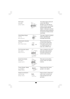
WiFi Header (11-pin WIFI) (see p.10 No. 25) USB+5V_2 NC NC GND2 NC+3SVB 1 GND1 NC D0-D0+ USB+5V_1 Infrared Module Header (5-pin IR1) (see p.10, No. 21) Internal Audio Connectors (4-pin CD1) (CD1: see p.10, No. 30) CD-L GND GND CD-R IRTX +5VSB DUMMY 1 GND IRRX CD1 This header supports WiFi+AP function with ASRock WiFi-802.11g or WiFi-802.11n module, an easy-to-use wireless local area network (WLAN) adapter. It allows you to create a wireless environment and enjoy the convenience of wireless network connectivity. This header supports an optional wireless transmitting and receiving infrared module. This connector allows you to receive stereo audio input from sound sources such as a CD-ROM, DVD-ROM, TV tuner card, or MPEG card. Front Panel Audio Header (8-pin AUDIO1) (see p.10, No. 27) System Panel Header (9-pin PANEL1) (see p.10, No. 19) Chassis Speaker Header (4-pin SPEAKER 1) (see p.10, No. 20) Chassis Fan Connector (3-pin CHA_FAN1) (see p.10, No. 23) GND BACKOUT-R BACKOUT-L 1 A U D - O U T- L GND A U D - O U T- R MIC-POWER MIC PLED+ PLEDPWRBTN# GND 1 DUMMY RESET# GND HDLEDHDLED+ 1 SPEAKER DUMMY DUMMY +5V GND +12V CHA_FAN_SPEED This is an interface for the front panel audio cable that allows convenient connection and control of audio devices. This header accommodates several system front panel functions. Please connect the chassis speaker to this header. Please connect a chassis fan cable to this connector and match the black wire to the ground pin. 20
-
 1
1 -
2
-
3
-
4
-
5
-
6
-
7
-
8
-
9
-
10
-
11
-
12
-
13
-
14
-
 15
15 -
 16
16 -
 17
17 -
 18
18 -
 19
19 -
 20
20 -
 21
21 -
 22
22 -
 23
23 -
 24
24 -
 25
25 -
26
-
27
-
28
-
29
-
30
-
31
-
32
-
33
-
34
-
35
-
36
-
37
-
38
-
39
-
40
-
41
-
42
-
43
-
44
-
45
-
46
-
47
-
48
-
49
-
50
-
51
-
52
-
53
-
54
-
55
-
56
-
57
 |
 |
