ASRock ALiveDual-eSATA2 User Manual - Page 16
Expansion Slots PCI Slots, PCI Express slot and AGP, Installing an expansion card - pci express 2 0
 |
View all ASRock ALiveDual-eSATA2 manuals
Add to My Manuals
Save this manual to your list of manuals |
Page 16 highlights
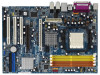
2.4 Expansion Slots (PCI Slots, PCI Express slot and AGP Slot) There are 3 PCI slots, 1 PCI Express slot and 1 AGP slot on ALiveDual-eSATA2 motherboard. PCI Slots: PCI slots are used to install expansion cards that have the 32-bit PCI interface. PCIE Slot: PCIE1 (PCIE x16 slot) is used for PCI Express cards with x16 lane width graphics cards. AGP Slot: The AGP slot is used to install a graphics card. The ASRock AGP slot has a special design of clasp that can securely fasten the inserted graphics card. 1. Please do NOT use a 3.3V AGP card on the AGP slot of this motherboard! It may cause permanent damage! For the voltage information of your AGP card, please check with the AGP card vendors. 2. If you plan to install Windows® VistaTM 32-bit / VistaTM 64-bit OS on this motherboard, please read the instructions and limitation on page 56 and 57 carefully. For Windows® 2000 / XP / XP 64-bit OS, there is no such limitation. Installing an expansion card Step 1. Before installing the expansion card, please make sure that the power supply is switched off or the power cord is unplugged. Please read the documentation of the expansion card and make necessary hardware settings for the card before you start the installation. Step 2. Remove the system unit cover (if your motherboard is already installed in a chassis). Step 3. Remove the bracket facing the slot that you intend to use. Keep the screws for later use. Step 4. Align the card connector with the slot and press firmly until the card is completely seated on the slot. Step 5. Fasten the card to the chassis with screws. Step 6. Replace the system cover. 16
-
 1
1 -
2
-
3
-
4
-
5
-
6
-
7
-
8
-
9
-
10
-
 11
11 -
 12
12 -
 13
13 -
 14
14 -
 15
15 -
 16
16 -
 17
17 -
 18
18 -
 19
19 -
 20
20 -
 21
21 -
22
-
23
-
24
-
25
-
26
-
27
-
28
-
29
-
30
-
31
-
32
-
33
-
34
-
35
-
36
-
37
-
38
-
39
-
40
-
41
-
42
-
43
-
44
-
45
-
46
-
47
-
48
-
49
-
50
-
51
-
52
-
53
-
54
-
55
-
56
-
57
 |
 |
