Alesis SR18 User Manual - Page 12
Rear Panel Physical Layout, Display Layout, Dc In, On/off Switch, Volume, Phones, Aux L / R - power supply
 |
View all Alesis SR18 manuals
Add to My Manuals
Save this manual to your list of manuals |
Page 12 highlights
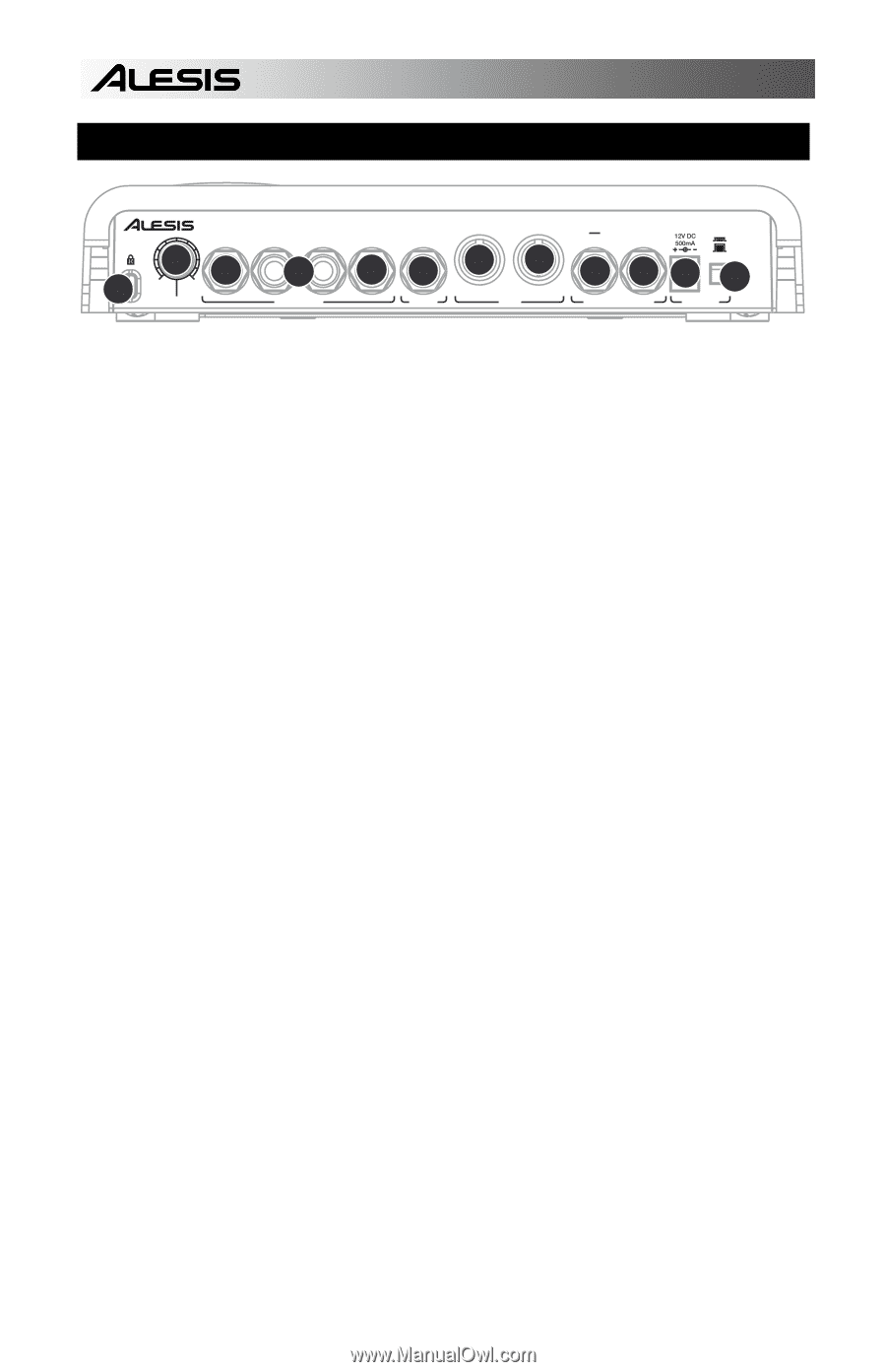
REAR PANEL PHYSICAL LAYOUT 12 AUX L/R MAIN RIGHT MAIN LEFT PHONES INSTRUMENT OUT / THRU IN 36 VOLUME 4 OUTPUTS 57 INPUT 89 MIDI START COUNT/A/B/FILL STOP ON OFF 10 11 1 2 FOOTSWITCHES POWER 1. DC IN - The supplied power adapter should be connected to a live outlet to power the unit. Alternatively, the unit may be powered with 6 AA batteries inserted in the bottom compartment. (Please refer to illustration in compartment for proper battery insertion). 2. ON/OFF SWITCH - This switch turns the unit on and off. 3. VOLUME - This knob controls the overall volume of the SR18. 4. ¼" TS RIGHT / LEFT OUTPUTS - These ¼" connections will output the audio from the SR18. Connect these outputs to an amplifier or a speaker system. For mono sound, you can connect only one output. 5. PHONES - Connect headphones to this output for quiet practicing. 6. AUX L / R - The SR18 can also output instrument layers through this auxiliary connection. For example, this allows you to output your drum and percussion tracks on separate channels, which can be useful in a recording / tracking situation. 7. INSTRUMENT - Connect your instruments (guitar, bass, etc.) to this ¼" input. The input signal will be mixed with the audio from the unit. 8. MIDI OUT / THRU - Use a five-pin MIDI cable to connect the MIDI OUT of the SR18 to the MIDI IN of an external MIDI device. 9. MIDI IN - Use a five-pin MIDI cable to connect the MIDI OUT of an external device to the MIDI IN of the SR18. 10. START / STOP FOOTSWITCH - Connect a ¼" TS footswitch to this input to remotely start and stop playback on the SR18. 11. COUNT / A / B / FILL - Connect a ¼" TS footswitch to this input to remotely control pattern playback on the SR18. 12. KENSINGTON LOCK - The SR18 may be secured to a table or surface, using this Kensington Lock slot. 12
-
 1
1 -
2
-
3
-
4
-
5
-
6
-
 7
7 -
 8
8 -
 9
9 -
 10
10 -
 11
11 -
 12
12 -
 13
13 -
 14
14 -
 15
15 -
 16
16 -
 17
17 -
18
-
19
-
20
-
21
-
22
-
23
-
24
-
25
-
26
-
27
-
28
-
29
-
30
-
31
-
32
-
33
-
34
-
35
-
36
-
37
-
38
-
39
-
40
-
41
-
42
-
43
-
44
-
45
-
46
-
47
-
48
-
49
-
50
-
51
-
52
-
53
-
54
-
55
-
56
-
57
-
58
-
59
-
60
 |
 |