Alesis iO4 Quick Start Guide - Page 4
Top Panel Features - 4 channel
 |
View all Alesis iO4 manuals
Add to My Manuals
Save this manual to your list of manuals |
Page 4 highlights
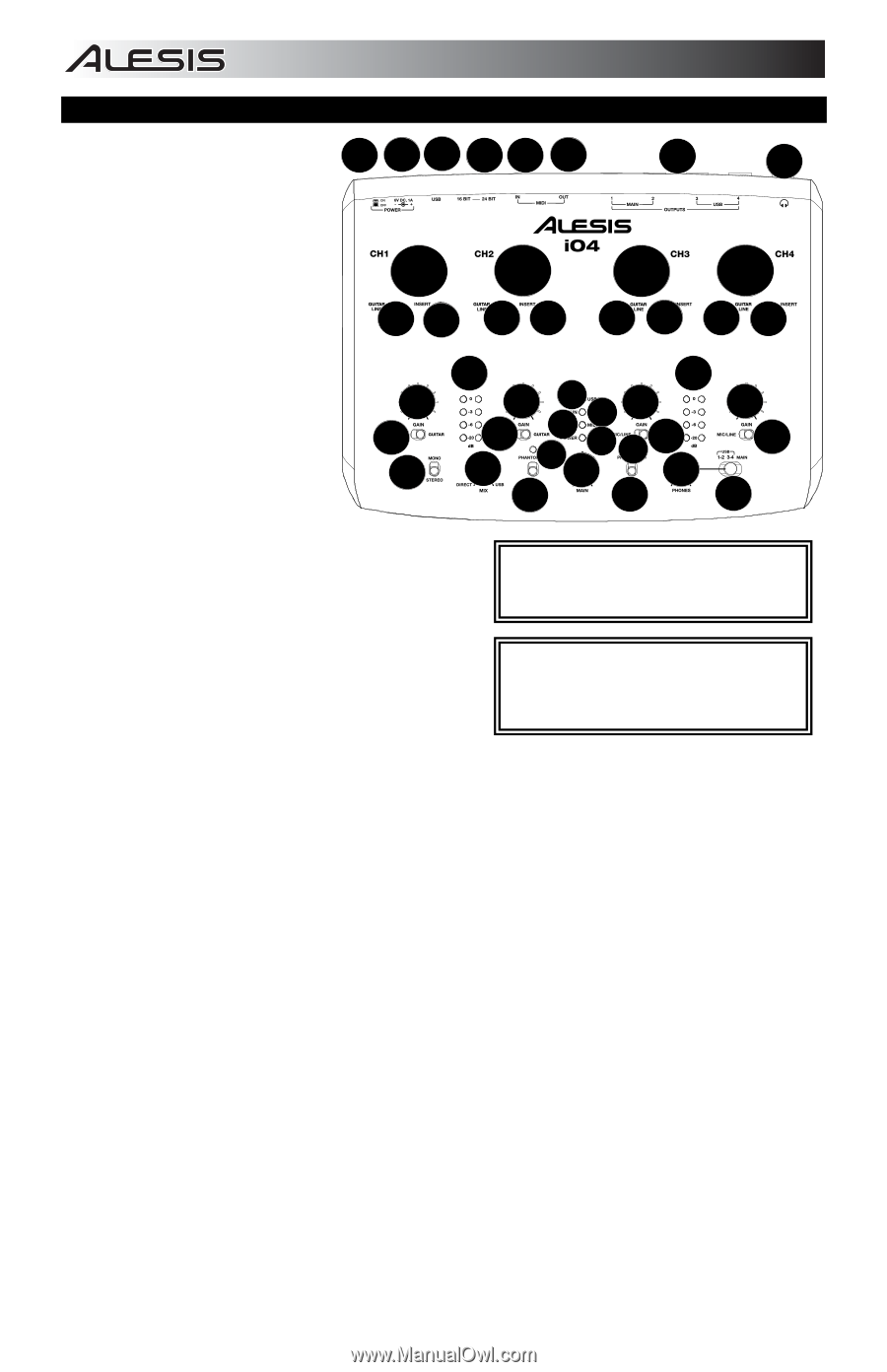
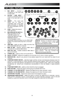
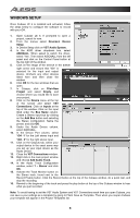
TOP PANEL FEATURES 1. MIC INPUT - Connect a microphone to this input with 26 25 24 23 22 21 20 19 an XLR cable. 2. GUITAR / LINE INPUT - Connect a line-level device or guitar to this input with a 1/4" cable. 3. INSERT - The insert jack 11 11 allows you to insert a compressor, EQ, or any other 23 23 23 23 signal processor in between the iO4's preamplifier and A/D converter. 4. GAIN - Adjusts the channel audio gain level. 5. MIC/LINE/GUITAR SWITCH - When this switch is in the "GUITAR" position, the channel will serve as a high- 15 16 4 5 10 5 11 4 6 87 13149 4 13 5 17 4 5 12 12 18 impedance input for connecting guitar or bass instruments. When the switch is in the "MIC/LINE" position, the channel will accept mic or line-level signals. 6. USB LED - Lights up when a USB connection has NOTE: Turning on phantom power will cause a momentary jump in the LED meters and a dropout in audio. been established with your computer. 7. MIDI IN LED - Flashes whenever MIDI data is received from an external MIDI device. 8. MIDI OUT LED - Flashes whenever MIDI data is sent out of the iO4. NOTE: Do not use the MIC INPUT and GUITAR/LINE INPUT at the same time on one channel. This may overload the channel and cause distortion. 9. POWER LED - Lights up when unit is powered on. 10. MONO / STEREO - Adjusts the headphone mix and main mix for mono or stereo operation. 11. MONITOR MIX - Blend in any amount of zero-latency signal from your inputs with the output of your computer. 12. PHANTOM POWER SWITCH - Individual toggle switches activate and deactivate phantom power for channels 1+2 and channels 3+4. When activated, phantom power supplies +48V to the XLR mic inputs. Please note that most dynamic microphones do not require phantom power, while most condenser microphones do. Consult your microphone's documentation to find out whether it needs phantom power. 13. PHANTOM POWER LED - Lights up when phantom power is engaged. 14. MAIN VOLUME - Adjusts the signal volume going to the MAIN OUTPUTS. 15. CHANNEL 1/2 VOLUME METER - Displays the signal level for input channels 1 and 2. 16. CHANNEL 3/4 VOLUME METER - Displays the signal level for input channels 3 and 4. 17. HEADPHONE VOLUME - Adjusts the volume level of the headphone output. 18. HEADPHONE MONITOR MIX - Adjust this switch to monitor the USB OUTPUT (channels 1 and 2), USB OUTPUT (channels 3 and 4), or the direct mix of 4 input channels: channels 1 and 3 in the left headphone output and channels 2 and 4 in the right headphone output and the USB output. 4
-
 1
1 -
 2
2 -
 3
3 -
 4
4 -
 5
5 -
 6
6 -
 7
7 -
 8
8 -
 9
9 -
 10
10 -
11
-
12
-
13
-
14
-
15
-
16
-
17
-
18
-
19
-
20
-
21
-
22
-
23
-
24
-
25
-
26
-
27
-
28
-
29
-
30
-
31
-
32
-
33
-
34
-
35
-
36
-
37
-
38
-
39
-
40
 |
 |