Asus AP110 AP110 User Manual - Page 26
Install System Memor
 |
View all Asus AP110 manuals
Add to My Manuals
Save this manual to your list of manuals |
Page 26 highlights
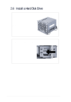
2.5 Install System Memor y DIMM Sockets Location The motherboard has three Dual Inline Memory Module (DIMM) sockets that support 3.3V SDRAM modules in 32, 64, 128, 256, 512MB, or 1GB densities. DIMM Sockets Install a DIMM 1. Unlock a DIMM socket by pressing the retaining clips outward. Align a DIMM on the socket such that the notches on the DIMM match the breaks on the socket. 2. Firmly insert the DIMM into the socket until the retaining clips snap back in place and the DIMM is properly seated. DIMM Notch Socket Break Installed DIMM CAUTION DIMMs are keyed with notches so that they fit in only one direction. DO NOT force a DIMM into a socket to avoid damaging the DIMM. 26 Chapter 3: Hardware Setup
-
 1
1 -
2
-
3
-
4
-
5
-
6
-
7
-
8
-
9
-
10
-
11
-
12
-
13
-
14
-
15
-
16
-
17
-
18
-
19
-
20
-
 21
21 -
 22
22 -
 23
23 -
 24
24 -
 25
25 -
 26
26 -
 27
27 -
 28
28 -
 29
29 -
 30
30 -
 31
31 -
32
-
33
-
34
-
35
-
36
-
37
-
38
-
39
-
40
-
41
-
42
-
43
-
44
-
45
-
46
-
47
-
48
-
49
-
50
 |
 |
26
Chapter 3:
Hardware Setup
2.5
Install System Memor
y
DIMM Sockets
Location
The motherboard has three Dual
Inline Memory Module (DIMM)
sockets that support 3.3V SDRAM
modules in 32, 64, 128, 256, 512MB,
or 1GB densities.
DIMM Sockets
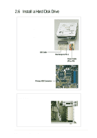
DIMM Notch
Socket Break
Install a DIMM
1.
Unlock a DIMM socket by
pressing the retaining clips
outward. Align a DIMM on the
socket such that the notches
on the DIMM match the breaks
on the socket.
2.
Firmly insert the DIMM into the
socket until the retaining clips
snap back in place and the
DIMM is properly seated.
Installed DIMM
DIMMs are keyed with notches so that they fit in only one
direction. DO NOT force a DIMM into a socket to avoid
damaging the DIMM.
CAUTION