Asus P I-XP6NP5 User Manual - Page 10
Iii. Installation
 |
View all Asus P I-XP6NP5 manuals
Add to My Manuals
Save this manual to your list of manuals |
Page 10 highlights
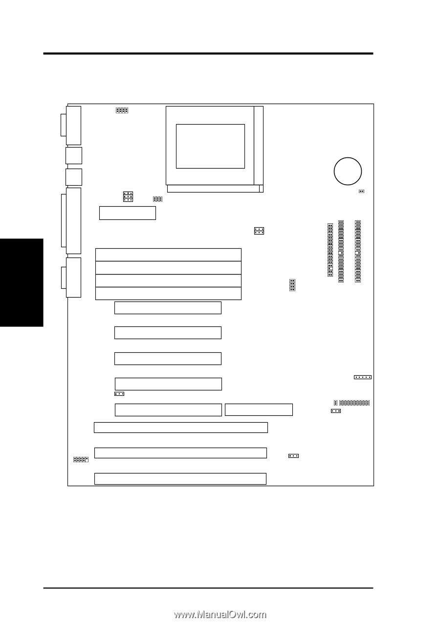
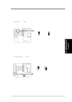
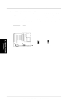
III. INSTALLATION (Map of Board) III. INSTALLATION Map of the ASUS Motherboard CPU Voltage ID JP1 JP2 JP3 JP4 CPU ZIF Socket 8 COM 1 PS/2 Mouse PS/2 Keyboard Parallel Printer COM 2 JP6 Reg/ATX 3.3V 12V Fan Power Board Power Input for ATX Power Supply SIMM Socket 4 (Bank 1) SIMM Socket 3 (Bank 1) SIMM Socket 2 (Bank 0) SIMM Socket 1 (Bank 0) PCI Slot 1 PCI Slot 2 PCI Slot 3 PCI Slot 4 JP14 Multi-I/O Enable/Disable PCI Slot 5 ISA Slot 1 ISA Slot 2 Universal Serial Bus (Reserved) ISA Slot 3 JP8 JP9 BUS Freq. #CR2032 3Volt Button Cell Battery JP7 Battery Test Lead Floppy Drives Secondary IDE Primary IDE JP10 JP11 JP12 JP13 Freq. Ratio MediaBus 2.0 Infrared Connector IDE LED Case Connector JP16 CMOS (Clear/Operate) JP17 ROM Program (Dis/En) 4 ASUS P/I-XP65NP5 User's Manual
-
 1
1 -
2
-
3
-
4
-
 5
5 -
 6
6 -
 7
7 -
 8
8 -
 9
9 -
 10
10 -
 11
11 -
 12
12 -
 13
13 -
 14
14 -
 15
15 -
16
-
17
-
18
-
19
-
20
-
21
-
22
-
23
-
24
-
25
-
26
-
27
-
28
-
29
-
30
-
31
-
32
-
33
-
34
-
35
-
36
-
37
-
38
-
39
-
40
-
41
-
42
-
43
-
44
-
45
-
46
-
47
-
48
-
49
-
50
-
51
-
52
-
53
-
54
-
55
-
56
-
57
-
58
-
59
-
60
-
61
-
62
-
63
-
64
 |
 |