Asus P I-XP6NP5 User Manual - Page 26
Floppy Drive Connector 34-pin block
 |
View all Asus P I-XP6NP5 manuals
Add to My Manuals
Save this manual to your list of manuals |
Page 26 highlights
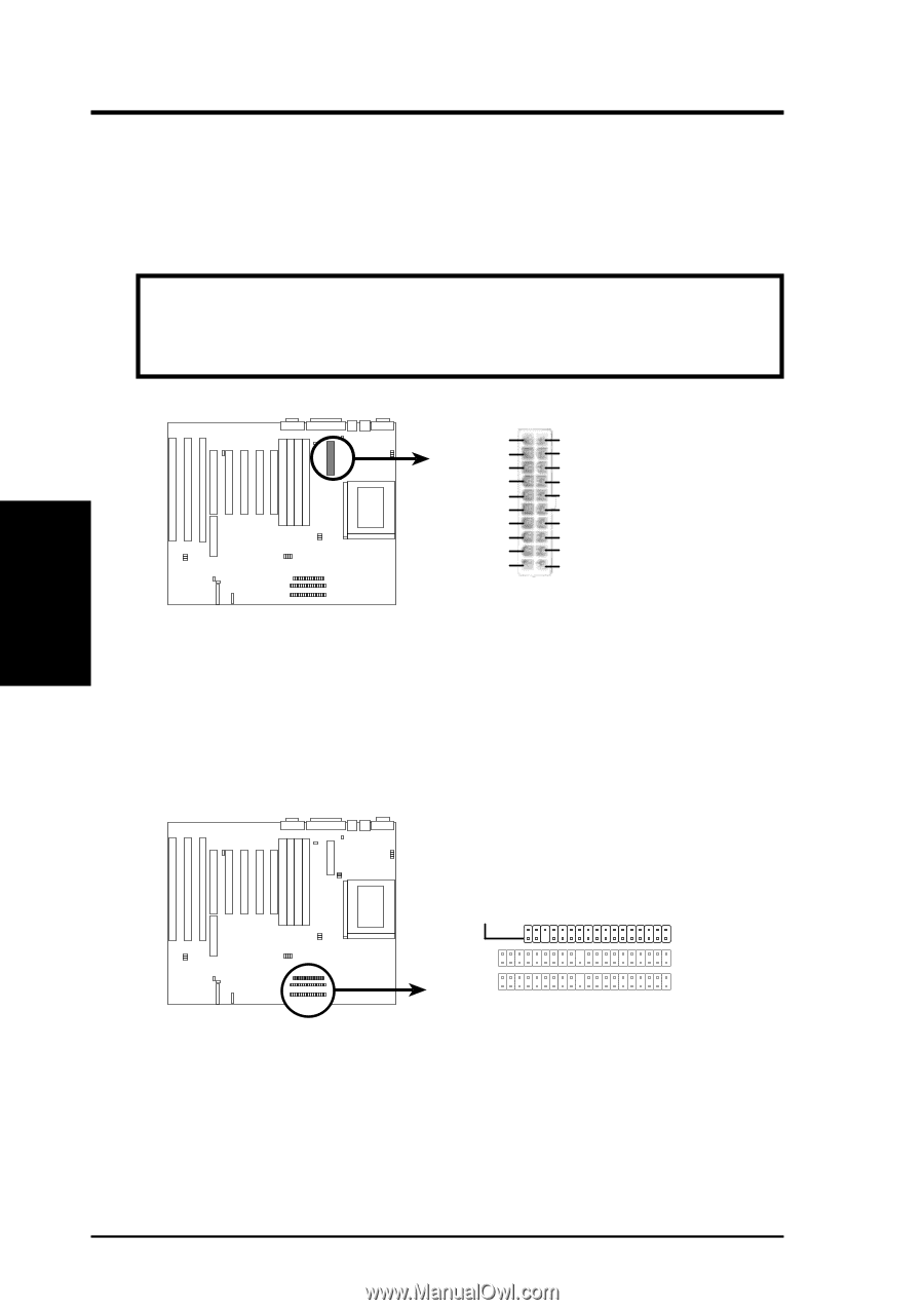
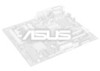
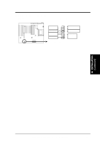
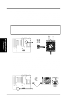
III. INSTALLATION 5. ATX Power Connector (20-pin block) This connector connects to a ATX power supply. The plug from the power supply will only insert in one orientation because of the different hole sizes. Find the proper orientation and push down firmly making sure that the pins are aligned. CAUTION: To prevent electrical spikes, make sure that the power supply is not connected to an outlet when making or removing connections. Power supplies contain power reserves which can damage electrical components. 12.0V 5VSB 5.0V 5.0V PW-0K GND -5.0V GND 5.0V GND GND 5.0V GND GND PS-ON GND 3.3V -12.0V 3.3V 3.3V ATX Power Connector on Motherboard 6. Floppy Drive Connector (34-pin block ) This connector supports the provided floppy drive ribbon cable. After connecting the single end to the board, connect the two plugs on the other end to one or two floppy drives. (Pin 5 is removed to prevent inserting in the wrong orientation when using ribbon cables with pin 5 plugged). Pin 1 Floppy Drive Connector III. INSTALLATION (Connectors) 20 ASUS P/I-XP6NP5 User's Manual
-
 1
1 -
2
-
3
-
4
-
5
-
6
-
7
-
8
-
9
-
10
-
11
-
12
-
13
-
14
-
15
-
16
-
17
-
18
-
19
-
20
-
 21
21 -
 22
22 -
 23
23 -
 24
24 -
 25
25 -
 26
26 -
 27
27 -
 28
28 -
 29
29 -
 30
30 -
 31
31 -
32
-
33
-
34
-
35
-
36
-
37
-
38
-
39
-
40
-
41
-
42
-
43
-
44
-
45
-
46
-
47
-
48
-
49
-
50
-
51
-
52
-
53
-
54
-
55
-
56
-
57
-
58
-
59
-
60
-
61
-
62
-
63
-
64
 |
 |