Asus P I-XP6NP5 User Manual - Page 11
ASUS P/I-XP6NP5 User's Manual, Jumpers, Expansion Slots, Connectors
 |
View all Asus P I-XP6NP5 manuals
Add to My Manuals
Save this manual to your list of manuals |
Page 11 highlights
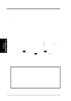
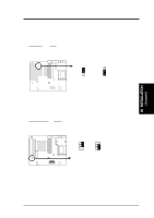
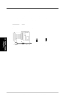
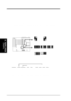
III. INSTALLATION (Map of Board) III. INSTALLATION Jumpers 1) JP14 2) JP17 3) JP16 4) JP7 5) JP8, JP9 6) JP10, 11, 12, 13 7) JP1, 2, 3, 4 8) JP6 p. 7 Multi-I/O Selection (Enable/Disable) p. 7 Flash ROM Boot Block Program (Enable/Disable) p. 8 Real Time Clock RAM (Operation/Clear Data) p. 9 Battery Test Lead (Operation/Test Mode) p. 10 CPU External Clock (BUS) Frequency Selection p. 10 CPU:BUS Frequency Ratio Selection p. 11 Voltage ID 3, 2, 1, 0 for CPU (2.1V to 3.5V) p. 11 3.3Volt Power Source (Regulator/ATX Supply) Expansion Slots 1) SIMM Sockets 2) ZIF Socket 8 3) ISA Slots 1, 2, 3 4) PCI Slots 1, 2, 3, 4 5) PCI 5 / MediaBus p. 12 DRAM Memory Expansion Sockets p. 15 Central Processing Unit (CPU) Socket p. 16 16-bit ISA Bus Expansion Slots p. 16 32-bit PCI Bus Expansion Slots p. 18 32-bit PCI Bus Slot and MediaBus 2.0 Connectors 1) PS2KB 2) PS2MOUSE 3) PRINTER 4) COM1, COM2 5) POWER 6) FLOPPY 7) IDE1, IDE2 8) IDELED 9) TB LED (CON1) 10) SMI (CON1) 11) PWR SW. (CON1) 12) RESET (CON1) 13) KEYLOCK (CON1) 14) SPEAKER (CON1) 15) FANPWR 16) IR p. 19 PS/2 Keyboard Connector (6-pin female) p. 19 PS/2 Mouse Connector (6-pin female) p. 19 Parallel Port Connector (25-pin female) p. 19 Serial Port COM1 & COM2 (9-pin male) p. 20 Motherboard ATX Power Connector (20-pin Block) p. 20 Floppy Drive Connector (34-pin Block) p. 21 Primary/Secondary IDE Connectors (40-pin Blocks) p. 21 IDE LED Activity Light (2-pins) p. 22 System Power Power LED (2-pins) p. 22 SMI Switch Lead (2-pins) p. 22 Power Switch for ATX Power Supply p. 22 Reset Switch Lead (2-pins) p. 22 Keyboard Lock Switch & System Power LED (5-pins) p. 23 Speaker Connector (4-pins) p. 24 CPU 12V Cooling Fan Connector (6-pins) p. 24 Infrared Port Module Connector (5-pins) ASUS P/I-XP6NP5 User's Manual 5
-
 1
1 -
2
-
3
-
4
-
5
-
 6
6 -
 7
7 -
 8
8 -
 9
9 -
 10
10 -
 11
11 -
 12
12 -
 13
13 -
 14
14 -
 15
15 -
 16
16 -
17
-
18
-
19
-
20
-
21
-
22
-
23
-
24
-
25
-
26
-
27
-
28
-
29
-
30
-
31
-
32
-
33
-
34
-
35
-
36
-
37
-
38
-
39
-
40
-
41
-
42
-
43
-
44
-
45
-
46
-
47
-
48
-
49
-
50
-
51
-
52
-
53
-
54
-
55
-
56
-
57
-
58
-
59
-
60
-
61
-
62
-
63
-
64
 |
 |
