Asus P I-XP6NP5 User Manual - Page 18
System Memory DRAM & SRAM
 |
View all Asus P I-XP6NP5 manuals
Add to My Manuals
Save this manual to your list of manuals |
Page 18 highlights
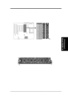
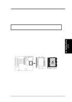
III. INSTALLATION (Memory) III. INSTALLATION 2. System Memory (DRAM & SRAM) This motherboard supports four 72-pin SIMMs (Single Inline Memory Modules) of 4MB, 8MB, 16MB, 32MB, 64MB to form a memory size between 8MB to 256MB. The DRAM can be either 60ns or 70ns Fast Page Mode (Asymmetric or Symmetric), Extended Data Output (EDO), or Burst Extended Data Output (BEDO). SIMMs must be installed in pairs so that each bank contains two of the same size memory modules. To support ECC, you must use true (opposed to phantom parity generated by TTL chips) 36-bit parity-type SIMM (e.g. 8 chips + 4 parity chips) in pairs for all modules. Mixing 32-bit non-parity SIMM (e.g. 8 chips) and 36-bit SIMM (e.g. 12 chips) will work minus the ECC feature. Install memory in any or all of the banks in any combination as follows: Bank Bank 0 SIMM Slots 1&2 Memory Module 4MB, 8MB, 16MB, 32MB, 64MB 72-pin FPM, EDO, BEDO SIMM Total Memory x2 Bank 1 4MB, 8MB, 16MB, 32MB, 64MB x2 SIMM Slots 3&4 72-pin FPM, EDO, BEDO SIMM Total System Memory = IMPORTANT: Each bank must have the same size and type (FPM, EDO, BEDO) of memory installed in pairs. IMPORTANT: Memory setup is required using "Auto Configuration" in Chipset Features Setup of the BIOS SOFTWARE. IMPORTANT: Each bank must have the same size memory installed in pairs. Do not use memory modules with more than 24 chips per module. Modules with more than 24 chips exceed the design specifications of the memory subsystem and will be unstable. 12 ASUS P/I-XP6NP5 User's Manual
-
 1
1 -
2
-
3
-
4
-
5
-
6
-
7
-
8
-
9
-
10
-
11
-
12
-
 13
13 -
 14
14 -
 15
15 -
 16
16 -
 17
17 -
 18
18 -
 19
19 -
 20
20 -
 21
21 -
 22
22 -
 23
23 -
24
-
25
-
26
-
27
-
28
-
29
-
30
-
31
-
32
-
33
-
34
-
35
-
36
-
37
-
38
-
39
-
40
-
41
-
42
-
43
-
44
-
45
-
46
-
47
-
48
-
49
-
50
-
51
-
52
-
53
-
54
-
55
-
56
-
57
-
58
-
59
-
60
-
61
-
62
-
63
-
64
 |
 |
