Asus P2E-VM P2E-VM User Manual - Page 30
Stereo Audio In Connectors 4-pin CD1, CD2, AUX
 |
View all Asus P2E-VM manuals
Add to My Manuals
Save this manual to your list of manuals |
Page 30 highlights
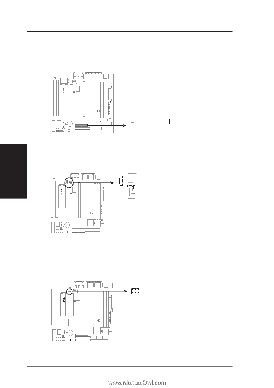
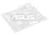
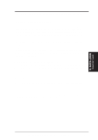
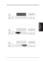
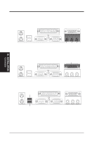
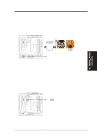
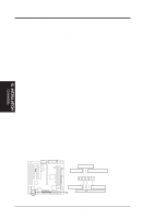
R R III. INSTALLATION Connectors III. INSTALLATION 11. Floppy Disk Drive Connector (34-1pin FLOPPY) This connector supports the provided floppy drive ribbon cable. After connecting the single end to the board, connect the two plugs on the other end to the floppy drives. (Pin 5 is removed to prevent inserting in the wrong orientation when using ribbon cables with pin 5 plugged). NOTE: Orient the red markings on the floppy ribbon cable to PIN 1 PIN 1 Floppy Disk Drive Connector P2L-VM/P2E-VM Floppy Disk Drive Connector 12. Stereo Audio In Connectors (4-pin CD1, CD2, AUX) CD1, CD2, and AUX connectors can be used to receive stereo audio input from an internal CD-ROM drive or other sound sources such as a TV tuner or MPEG card. L G G R AUX Right Audio Channel Ground Ground Left Audio Channel CD1 CD2 Left Audio Channel Ground Ground Right Audio Channel NOTE: AUX has the same pin definitions as CD1 P2L-VM/P2E-VM Stereo Audio In Connectors 13. Digital Audio Interface (6-pin) This connector is the digital link between the motherboard and your audio devices such as CD player, sampler, or DAT recorder. It allows the digital transmission of audio data in SPDIF (Sony/Philips Digital Interface) Format. SPDIF SPDIFI: Digital Signal IN SPDIFO: Digital Signal OUT TTL: Short this, if output device is TTL level R P2L-VM/P2E-VM Digital Audio Interface 30 ASUS P2L-VM/P2E-VM User's Manual
-
 1
1 -
2
-
3
-
4
-
5
-
6
-
7
-
8
-
9
-
10
-
11
-
12
-
13
-
14
-
15
-
16
-
17
-
18
-
19
-
20
-
21
-
22
-
23
-
24
-
 25
25 -
 26
26 -
 27
27 -
 28
28 -
 29
29 -
 30
30 -
 31
31 -
 32
32 -
 33
33 -
 34
34 -
 35
35 -
36
-
37
-
38
-
39
-
40
-
41
-
42
-
43
-
44
-
45
-
46
-
47
-
48
-
49
-
50
-
51
-
52
-
53
-
54
-
55
-
56
-
57
-
58
-
59
-
60
-
61
-
62
-
63
-
64
-
65
-
66
-
67
-
68
-
69
-
70
-
71
-
72
-
73
-
74
-
75
-
76
-
77
-
78
-
79
-
80
-
81
-
82
-
83
-
84
-
85
-
86
-
87
-
88
-
89
-
90
-
91
-
92
-
93
-
94
-
95
-
96
-
97
-
98
-
99
-
100
-
101
-
102
-
103
-
104
-
105
-
106
-
107
-
108
-
109
-
110
-
111
-
112
-
113
-
114
-
115
-
116
 |
 |