Asus P2V-B P2V-B User Manual - Page 34
ASUS P2V-B User's Manual, Wake-On-Ring Connector 2-pin WOR, IMPORTANT, PWR UP On Modem Act, Chassis
 |
View all Asus P2V-B manuals
Add to My Manuals
Save this manual to your list of manuals |
Page 34 highlights
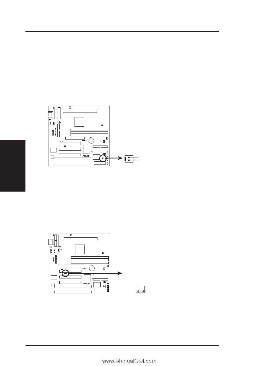
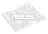
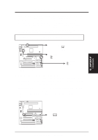
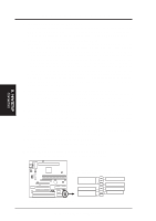
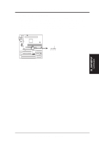
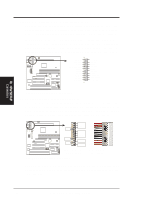
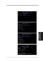
III. HARDWARE SETUP 18. Wake-On-Ring Connector (2-pin WOR) This connector connects to internal modem cards with a Wake-On-Ring output. The connector powers up the system when a ringup packet or signal is received through the internal modem card. NOTE: For external modems, Wake-On-Ring is detected through the COM port. IMPORTANT: This feature requires that PWR UP On Modem Act Power Up Control is set to Enabled (see Power Management Setup under BIOS SETUP) and that your system has an ATX power supply with at least 720mA +5V standby power. III. H/W SETUP Connectors P2V-B R WOR Pin 2 PIXRI# Pin 1 Ground P2V-B Wake-On-Ring Connector 19. Chassis Intrusion Sensor Lead (4-1 pin CHASIS) This lead is for a chassis intrusion monitor or sensor. The sensor is triggered when a high level signal is sent to the "chassis signal" lead. This occurs when a panel switch or light detector is triggered. This function requires the optional ASUS CIDB Chassis Intrusion Photo Sensor Module (see APPENDIX) to be installed. +5Volt Power Supply Standby Chassis Signal Ground P2V-B R P2V-B Chassis Intrusion Sensor Lead 34 ASUS P2V-B User's Manual
-
 1
1 -
2
-
3
-
4
-
5
-
6
-
7
-
8
-
9
-
10
-
11
-
12
-
13
-
14
-
15
-
16
-
17
-
18
-
19
-
20
-
21
-
22
-
23
-
24
-
25
-
26
-
27
-
28
-
 29
29 -
 30
30 -
 31
31 -
 32
32 -
 33
33 -
 34
34 -
 35
35 -
 36
36 -
 37
37 -
 38
38 -
 39
39 -
40
-
41
-
42
-
43
-
44
-
45
-
46
-
47
-
48
-
49
-
50
-
51
-
52
-
53
-
54
-
55
-
56
-
57
-
58
-
59
-
60
-
61
-
62
-
63
-
64
-
65
-
66
-
67
-
68
-
69
-
70
-
71
-
72
-
73
-
74
-
75
-
76
-
77
-
78
-
79
-
80
-
81
-
82
-
83
-
84
-
85
-
86
-
87
-
88
-
89
-
90
-
91
-
92
-
93
-
94
-
95
-
96
 |
 |