Asus P5GDC Pro User Manual - Page 51
Serial ATA Master/Slave connectors
 |
View all Asus P5GDC Pro manuals
Add to My Manuals
Save this manual to your list of manuals |
Page 51 highlights
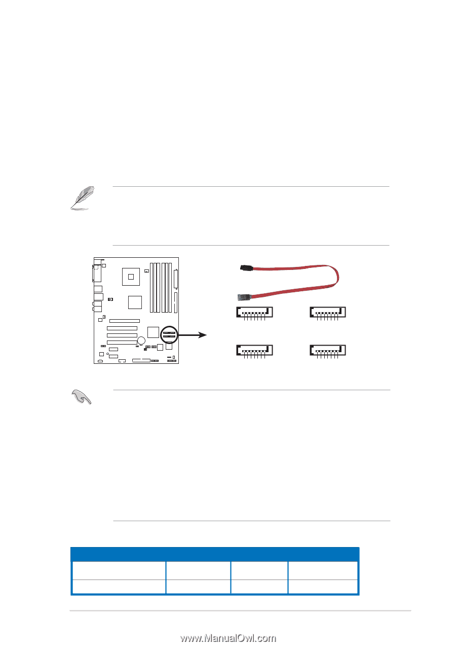
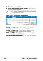
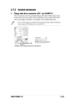
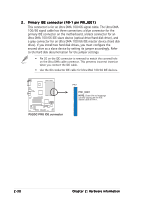
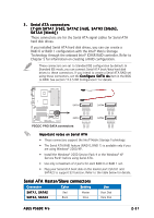
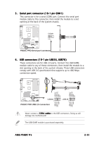
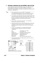
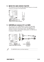
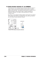
3. Serial ATA connectors (7-pin SATA1 [red], SATA2 [red], SATA3 [black], SATA4 [black]) These connectors are for the Serial ATA signal cables for Serial ATA hard disk drives. If you installed Serial ATA hard disk drives, you can can create a RAID 0 or RAID 1 configuration with the Intel® Matrix Storage Technology through the onboard Intel® ICH6R RAID controller. Refer to Chapter 5 for information on creating a RAID configuration. These connectors are set to Standard IDE configuration by default. In Standard IDE mode, you can connect Serial ATA boot/data hard disk drives to these connectors. If you intend to create a Serial ATA RAID set using these connectors, set the C o n f i g u r e S A T A A s item in the BIOS to RAID. See section "4.3.5 IDE Configuration" for details. P5GDC PRO SATA3 SATA4 GND RSATA_TXP4 RSATA_TXN4 GND RSATA_RXP4 RSATA_RXN4 GND GND RSATA_TXP3 RSATA_TXN3 GND RSATA_RXP3 RSATA_RXN3 GND SATA1 SATA2 GND RSATA_TXP2 RSATA_TXN2 GND RSATA_RXP2 RSATA_RXN2 GND GND RSATA_TXP1 RSATA_TXN1 GND RSATA_RXP1 RSATA_RXN1 GND P5GDC PRO SATA connectors Important notes on Serial ATA • These connectors support the Intel® Matrix Storage Technology. • The Serial ATA RAID feature (RAID 0, RAID 1) is available only if you are using Windows® 2000/XP. • Install the Windows® 2000 Service Pack 4 or the Windows® XP Service Pack1 before using Serial ATA. • Use only a maximum of 2 ports for each RAID 0 or RAID 1 set. • Plug your Serial ATA boot disk on the master port (SATA1 and SATA2) to support S3 function. Refer to the table below for details. Serial ATA Master/Slave connectors Connector Color Setting SATA1, SATA2 Red Master SATA3, SATA4 Black Slave Use Boot Disk Data Disk ASUS P5GDC Pro 2-31
-
 1
1 -
2
-
3
-
4
-
5
-
6
-
7
-
8
-
9
-
10
-
11
-
12
-
13
-
14
-
15
-
16
-
17
-
18
-
19
-
20
-
21
-
22
-
23
-
24
-
25
-
26
-
27
-
28
-
29
-
30
-
31
-
32
-
33
-
34
-
35
-
36
-
37
-
38
-
39
-
40
-
41
-
42
-
43
-
44
-
45
-
 46
46 -
 47
47 -
 48
48 -
 49
49 -
 50
50 -
 51
51 -
 52
52 -
 53
53 -
 54
54 -
 55
55 -
 56
56 -
57
-
58
-
59
-
60
-
61
-
62
-
63
-
64
-
65
-
66
-
67
-
68
-
69
-
70
-
71
-
72
-
73
-
74
-
75
-
76
-
77
-
78
-
79
-
80
-
81
-
82
-
83
-
84
-
85
-
86
-
87
-
88
-
89
-
90
-
91
-
92
-
93
-
94
-
95
-
96
-
97
-
98
-
99
-
100
-
101
-
102
-
103
-
104
-
105
-
106
-
107
-
108
-
109
-
110
-
111
-
112
-
113
-
114
-
115
-
116
-
117
-
118
-
119
-
120
-
121
-
122
-
123
-
124
-
125
-
126
-
127
-
128
-
129
-
130
 |
 |