Asus P9D-X User Guide - Page 26
Layout contents, Jumpers, Rear panel connectors, Slots/Sockets, Onboard LEDs - cpu
 |
View all Asus P9D-X manuals
Add to My Manuals
Save this manual to your list of manuals |
Page 26 highlights
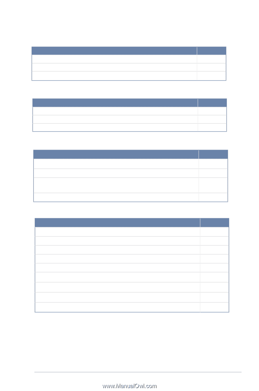
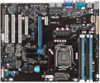
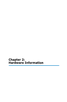
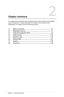
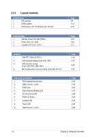
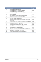
2.2.4 Layout contents Slots/Sockets 1. CPU sockets 2. DDR3 sockets 3. PCI Express x16 / PCI Express x8 / PCI slot Onboard LEDs 1. Standby Power LED (SB_PWR1) 2. Power LED (+5V_LED) 3. Location LED (LOC_LED1) Jumpers 1. Clear RTC RAM (CLRTC1) 2. VGA controller setting (3-pin VGA_SW1) 3. LAN controller setting (3-pin LAN_SW1, LAN_SW2,) 4. ME firmware force recovery setting (3-pin ME_RCVR1) Rear panel connectors 1. PS/2 keyboard/mouse port 2. USB 3.0 ports 1 and 2 3. COM1 port 4. Video Graphics Adapter port 5. RJ-45 ports for LAN 6. Power-on Button 7. Location LED 8. Power LED 9. USB 2.0 ports 1 and 2 Page 2-8 2-14 2-18 Page 2-20 2-20 2-21 Page 2-22 2-23 2-23 2-24 Page 2-25 2-25 2-25 2-25 2-25 2-25 2-25 2-25 2-25 2-6 Chapter 2: Hardware information
-
 1
1 -
2
-
3
-
4
-
5
-
6
-
7
-
8
-
9
-
10
-
11
-
12
-
13
-
14
-
15
-
16
-
17
-
18
-
19
-
20
-
 21
21 -
 22
22 -
 23
23 -
 24
24 -
 25
25 -
 26
26 -
 27
27 -
 28
28 -
 29
29 -
 30
30 -
 31
31 -
32
-
33
-
34
-
35
-
36
-
37
-
38
-
39
-
40
-
41
-
42
-
43
-
44
-
45
-
46
-
47
-
48
-
49
-
50
-
51
-
52
-
53
-
54
-
55
-
56
-
57
-
58
-
59
-
60
-
61
-
62
-
63
-
64
-
65
-
66
-
67
-
68
-
69
-
70
-
71
-
72
-
73
-
74
-
75
-
76
-
77
-
78
-
79
-
80
-
81
-
82
-
83
-
84
-
85
-
86
-
87
-
88
-
89
-
90
-
91
-
92
-
93
-
94
-
95
-
96
-
97
-
98
-
99
-
100
-
101
-
102
-
103
-
104
-
105
-
106
-
107
-
108
-
109
-
110
-
111
-
112
-
113
-
114
-
115
-
116
-
117
-
118
-
119
-
120
-
121
-
122
-
123
-
124
-
125
-
126
-
127
-
128
-
129
-
130
-
131
-
132
-
133
-
134
-
135
-
136
-
137
-
138
-
139
-
140
-
141
-
142
-
143
-
144
-
145
-
146
-
147
-
148
-
149
-
150
-
151
-
152
 |
 |