Asus ROG STRIX H270F GAMING STRIX H270F GAMING Users manual English - Page 17
Layout contents, Connectors/Jumpers/Buttons and switches/Slots/LEDs
 |
View all Asus ROG STRIX H270F GAMING manuals
Add to My Manuals
Save this manual to your list of manuals |
Page 17 highlights
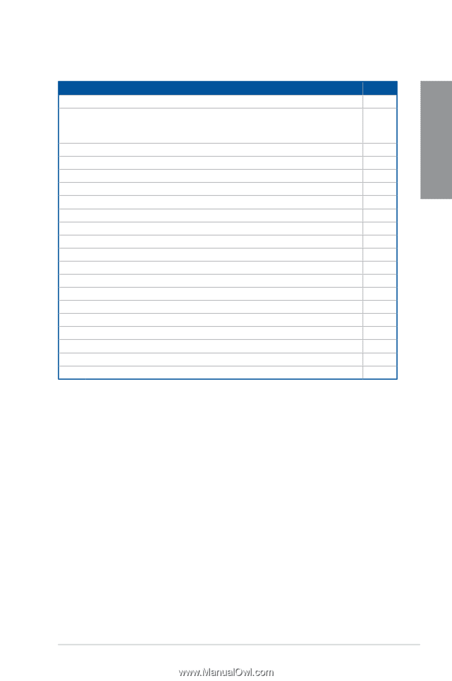
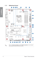
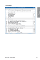
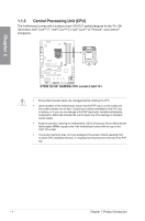
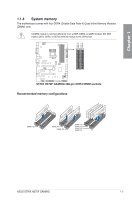
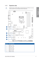
Chapter 1 Layout contents Connectors/Jumpers/Buttons and switches/Slots/LEDs 1. ATX power connectors (24-pin EATXPWR, 8-pin EATX12V) 2. CPU, CPU optional, AIO pump, extension, and chassis fan connectors (4-pin CPU_FAN, 4-pin CPU_OPT, 4-pin AIO_PUMP, 5-pin EXT_FAN, 4-pin CHA_FAN1~2) 3. M.2 sockets (M.2_1~2) 4. LGA1151 CPU socket 5. DDR4 DIMM slots 6. POST State LEDs 7. RGB LED 8. 3D Mount holes 9. USB 3.0 connectors (20-1 pin USB3_12, USB3_34) 10. Intel® Serial ATA 6 Gb/s connectors (7-pin SATA6G_1~6) 11. Standby power LED (SB_PWR) 12. Clear RTC RAM jumper (2-pin CLRTC) 13. System panel connector (20-5 pin PANEL) 14. Thermal sensor cable connector (2-pin T_SENSOR) 15. USB 2.0 connectors (10-1 pin USB1112, USB1314) 16. ROG Extension connector (18-1 pin ROG_EXT) 17. TPM connector (14-1 pin TPM) 18. RGB header (4-pin RGB_HEADER) 19. Serial port connector (10-1 pin COM) 20. Front panel audio connector (10-1 pin AAFP) Page 1-17 1-16 1-20 1-4 1-5 1-10 1-11 1-10 1-14 1-13 1-11 1-9 1-18 1-20 1-15 1-15 1-19 1-21 1-19 1-14 ASUS STRIX H270F GAMING 1-3
-
 1
1 -
2
-
3
-
4
-
5
-
6
-
7
-
8
-
9
-
10
-
11
-
 12
12 -
 13
13 -
 14
14 -
 15
15 -
 16
16 -
 17
17 -
 18
18 -
 19
19 -
 20
20 -
 21
21 -
 22
22 -
23
-
24
-
25
-
26
-
27
-
28
-
29
-
30
-
31
-
32
-
33
-
34
-
35
-
36
-
37
-
38
-
39
-
40
-
41
-
42
-
43
-
44
-
45
-
46
-
47
-
48
-
49
-
50
-
51
-
52
-
53
-
54
-
55
-
56
-
57
-
58
-
59
-
60
-
61
-
62
-
63
-
64
-
65
-
66
-
67
-
68
-
69
-
70
-
71
-
72
-
73
-
74
-
75
-
76
-
77
-
78
-
79
-
80
-
81
-
82
-
83
-
84
-
85
-
86
-
87
-
88
-
89
-
90
-
91
-
92
-
93
-
94
-
95
-
96
-
97
-
98
-
99
-
100
-
101
-
102
-
103
-
104
-
105
-
106
-
107
-
108
-
109
-
110
-
111
-
112
-
113
 |
 |