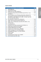
Asus ROG STRIX X399-E GAMING User Guide - Page 16
Motherboard layout, 1.8 Internal connectors, 3.1 Rear I/O connection
 |
View all Asus ROG STRIX X399-E GAMING manuals
Add to My Manuals
Save this manual to your list of manuals |
Page 16 highlights
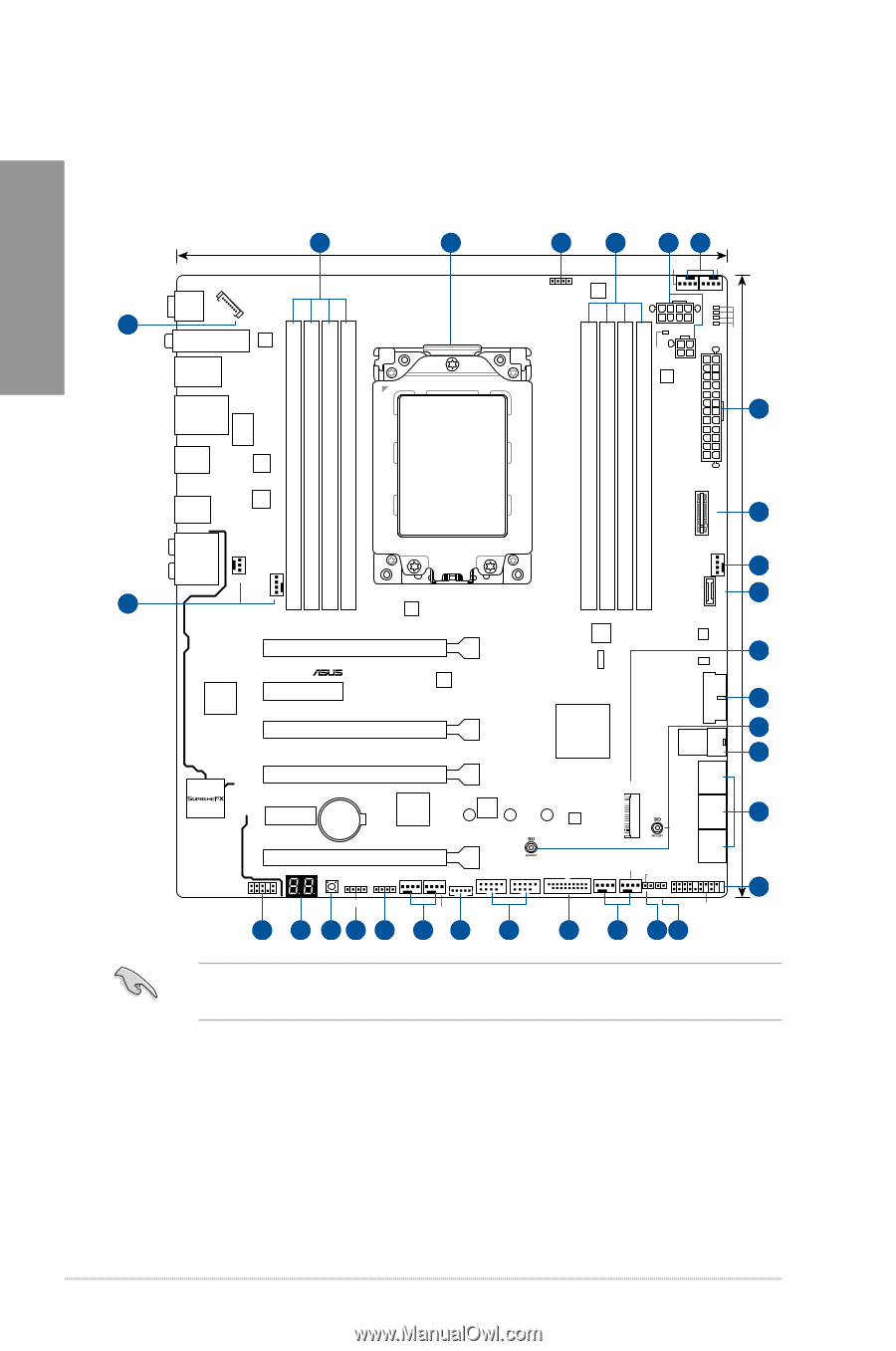
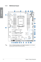
Chapter 1 1.1.2 Motherboard layout 20 5 BIOS_FLBK LED_CON M.2(WIFI) DIGI+ U31G1_5-8 LAN_U31G1_34 1 26.9cm(10.6in) 2 3 1 RGB_HEADER2 DIGI+ EPU 45 CPU_OPT CPU_FAN EATX12V_1 EATX12V_2 DIGI+ DRAM CPU VGA BOOT 4 30.4cm(12.0in) EATXPWR DDR4 DIMM_A2 (64bit, 288-pin module) DDR4 DIMM_A1 (64bit, 288-pin module) DDR4 DIMM_B2 (64bit, 288-pin module) DDR4 DIMM_B1 (64bit, 288-pin module) PLUG_8PIN_PWR1 LANGuard AIO_PUMP DDR4 DIMM_D1 (64bit, 288-pin module) DDR4 DIMM_D2 (64bit, 288-pin module) DDR4 DIMM_C1 (64bit, 288-pin module) DDR4 DIMM_C2 (64bit, 288-pin module) M.2_2(SOCKET3) U31G1_12 Intel I211-AT SocketTR4 ASM U31G2_EA2 U31G2_EC1 3142 6 AUDIO COV_FAN BIOS Super I/O PCIEX16_1 PCIEX4 DIGI+ EPU STRIX X399-E GAMING PCIEX8_2 ICS ASM 1480 AMD® X399 PCIEX16_3 PCIEX1 Lithium Cell CMOS Power ROG TPU 2280 2260 2242 AURA M.2_1(SOCKET3) U31G2_C1 CHA_FAN1 5 7 ASM 1543 ASM 1562 U.2 U31G1_910 6 8 9 10 11 SATA6G_5 SATA6G_3 SATA6G_1 SATA6G_6 SATA6G_4 SATA6G_2 AAFP 19 PCIEX8_4 Q_CODE PWR_SW CHA_FAN3 RGB_HEADER1 USB12 EXT_FAN USB34 ADD_HEADER CHA_FAN2 18 17 16 3 5 5 15 M.2_FAN U31G1_1112 W_PUMP+ T_SENSOR1 CLRTC 8 5 14 13 PANEL 12 Refer to 1.1.8 Internal connectors and 2.3.1 Rear I/O connection for more information about rear panel connectors and internal connectors. 1-2 Chapter 1: Product Introduction
-
 1
1 -
2
-
3
-
4
-
5
-
6
-
7
-
8
-
9
-
10
-
 11
11 -
 12
12 -
 13
13 -
 14
14 -
 15
15 -
 16
16 -
 17
17 -
 18
18 -
 19
19 -
 20
20 -
 21
21 -
22
-
23
-
24
-
25
-
26
-
27
-
28
-
29
-
30
-
31
-
32
-
33
-
34
-
35
-
36
-
37
-
38
-
39
-
40
-
41
-
42
-
43
-
44
-
45
-
46
-
47
-
48
-
49
-
50
-
51
-
52
-
53
-
54
-
55
-
56
-
57
-
58
-
59
-
60
-
61
-
62
-
63
-
64
-
65
-
66
-
67
-
68
-
69
-
70
-
71
-
72
-
73
-
74
-
75
-
76
-
77
-
78
-
79
-
80
-
81
-
82
-
83
-
84
-
85
-
86
-
87
-
88
-
89
-
90
-
91
-
92
-
93
-
94
-
95
-
96
-
97
-
98
-
99
-
100
 |
 |