Asus TS300-E10-PS4 User Manual - Page 39
-inch drives, 2.6.1 Installing a 5.25-inch drive
 |
View all Asus TS300-E10-PS4 manuals
Add to My Manuals
Save this manual to your list of manuals |
Page 39 highlights
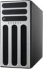
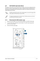
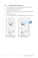
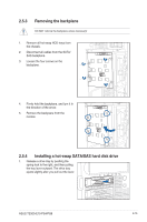
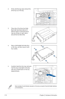
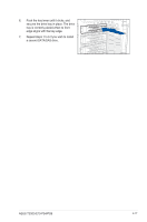
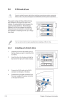
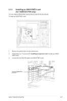
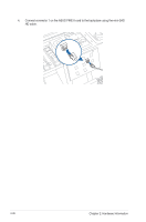
2.6 5.25-inch drives Ensure to unplug the power cable before installing or removing any system components. Failure to do so may cause damage to the motherboard and other system components! The system comes with three 5.25-inch drive bays located on the upper front part of the chassis. An optional optical drive occupies the uppermost bay (labeled 1). The lower bays (labeled 2 and 3) are available for additional 5.25-inch drives or 5.25-inch to 3.5-inch hard drive adapter for installing 3.5-inch zip or floppy disk drives. You must remove the front panel assembly before installing a 5.25-inch drive. 2.6.1 Installing a 5.25-inch drive 1. Unscrew and remove the metal cover of the bay where you want to install the 5.25inch drive. 2. Insert the drive into the bay and slide the bay lock to the right until it clicks in place. 3. Connect the SATA cable to the SATA connector on the back of the drive. 4. Connect the 4-pin power connector from the power supply to the power connector on the back of the drive. 2-18 Chapter 2: Hardware Information
-
 1
1 -
2
-
3
-
4
-
5
-
6
-
7
-
8
-
9
-
10
-
11
-
12
-
13
-
14
-
15
-
16
-
17
-
18
-
19
-
20
-
21
-
22
-
23
-
24
-
25
-
26
-
27
-
28
-
29
-
30
-
31
-
32
-
33
-
 34
34 -
 35
35 -
 36
36 -
 37
37 -
 38
38 -
 39
39 -
 40
40 -
 41
41 -
 42
42 -
 43
43 -
 44
44 -
45
-
46
-
47
-
48
-
49
-
50
-
51
-
52
-
53
-
54
-
55
-
56
-
57
-
58
-
59
-
60
-
61
-
62
-
63
-
64
-
65
-
66
-
67
-
68
-
69
-
70
-
71
-
72
-
73
-
74
-
75
-
76
-
77
-
78
-
79
-
80
-
81
-
82
-
83
-
84
-
85
-
86
-
87
-
88
-
89
-
90
-
91
-
92
-
93
-
94
-
95
-
96
-
97
-
98
-
99
-
100
-
101
-
102
-
103
-
104
-
105
-
106
-
107
-
108
-
109
-
110
-
111
-
112
-
113
-
114
-
115
-
116
-
117
-
118
-
119
-
120
-
121
-
122
-
123
-
124
-
125
-
126
-
127
-
128
-
129
-
130
-
131
-
132
-
133
-
134
-
135
-
136
-
137
-
138
-
139
-
140
-
141
-
142
-
143
-
144
-
145
-
146
-
147
-
148
-
149
-
150
-
151
-
152
-
153
-
154
-
155
-
156
-
157
-
158
-
159
-
160
-
161
-
162
-
163
 |
 |
