Asus TUF Z370-PLUS GAMING User Guide - Page 27
TUF Z370-PLUS GAMING USB2.0 connectors, TUF Z370-PLUS GAMING Analog front panel connector
 |
View all Asus TUF Z370-PLUS GAMING manuals
Add to My Manuals
Save this manual to your list of manuals |
Page 27 highlights
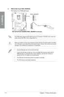
Chapter 1 2. Front panel audio connector (10-1 pin AAFP) This connector is for a chassis-mounted front panel audio I/O module that supports HD Audio. Connect one end of the front panel audio I/O module cable to this connector. AGND NC SENSE1_RETUR SENSE2_RETUR ® TUF Z370-PLUS GAMING AAFP PORT1 L PORT1 R PORT2 R SENSE_SEND PORT2 L HD-audio-compliant pin definition TUF Z370-PLUS GAMING Analog front panel connector We recommend that you connect a high-definition front panel audio module to this connector to avail of the motherboard's high-definition audio capability. 3. USB 2.0 connectors (10-1 pin USB1112; USB1314) These connectors are for USB 2.0 ports. Connect the USB module cable to these connectors, then install the module to a slot opening at the back of the system chassis. This USB connector complies with USB 2.0 specification that supports up to 480 Mb/s connection speed. USB+5V USB_P13USB_P13+ GND NC ® TUF Z370-PLUS GAMING USB1112 USB1314 USB+5V USB_P11USB_P11+ GND NC PIN 1 PIN 1 USB+5V USB_P14USB_P14+ GND USB+5V USB_P12USB_P12+ GND TUF Z370-PLUS GAMING USB2.0 connectors DO NOT connect a 1394 cable to the USB connectors. Doing so will damage the motherboard! The USB 2.0 module is purchased separately. ASUS TUF Z370-PLUS GAMING 1-13
-
 1
1 -
2
-
3
-
4
-
5
-
6
-
7
-
8
-
9
-
10
-
11
-
12
-
13
-
14
-
15
-
16
-
17
-
18
-
19
-
20
-
21
-
 22
22 -
 23
23 -
 24
24 -
 25
25 -
 26
26 -
 27
27 -
 28
28 -
 29
29 -
 30
30 -
 31
31 -
 32
32 -
33
-
34
-
35
-
36
-
37
-
38
-
39
-
40
-
41
-
42
-
43
-
44
-
45
-
46
-
47
-
48
-
49
-
50
-
51
-
52
-
53
-
54
-
55
-
56
-
57
-
58
-
59
-
60
-
61
-
62
-
63
-
64
-
65
-
66
-
67
-
68
-
69
-
70
-
71
-
72
-
73
-
74
-
75
-
76
-
77
-
78
-
79
-
80
-
81
-
82
-
83
-
84
-
85
-
86
-
87
-
88
-
89
-
90
-
91
-
92
-
93
-
94
-
95
-
96
-
97
-
98
-
99
-
100
-
101
-
102
-
103
-
104
-
105
 |
 |
