Asus TX97-N TX97-N User Manual - Page 25
LAN Activity Connectors 2-pin LAN_LED & 3-pin WOL_CON
 |
View all Asus TX97-N manuals
Add to My Manuals
Save this manual to your list of manuals |
Page 25 highlights
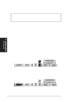
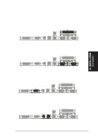
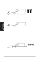
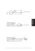
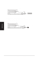
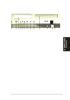
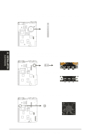
III. INSTALLATION (Connectors) III. INSTALLATION 11. Primary IDE Connector (40-1pin IDE) This connector supports the provided IDE hard disk drive ribbon cable. After connecting one end to the riser card, connect the other end to a hard disk drive. The primary IDE channel supports both a master and a slave IDE device but the system housing size only permits a standard IDE hard drive to be installed. IDE (Hard Disk Drive) Connector Primary IDE Connector Pin 1 Orient the red stripe on the IDE ribbon cable to Pin 1 12. 3.5inch Floppy Disk Drive Connector (34-1pin FLOPPY) This connector supports the provided floppy drive ribbon cable. After connecting the single end to the riser card, connect the other end to a 3.5inch floppy disk drive. Riser Card Front Floppy Disk Drive Connector Floppy Drive Conn. Riser Slot Panel Conn. Pin 1 Orient the red stripe on the floppy ribbon cable to Pin 1 13. LAN Activity Connectors (2-pin LAN_LED & 3-pin WOL_CON) These connectors support Local Area Network (LAN) cards such as the ASUS PCI-L101 with output signals for data transfer activity. The LAN_LED connector allows the front panel LED to blink during transfer activity between the network and the computer. The WOL_CON connector allows the system to power up when there is a wakeup package (signal) received from the network. LAN activity LED Riser Card Front LAN Activity Connectors Riser Slot Wake on LAN activity ASUS TX97-N User's Manual 25
-
 1
1 -
2
-
3
-
4
-
5
-
6
-
7
-
8
-
9
-
10
-
11
-
12
-
13
-
14
-
15
-
16
-
17
-
18
-
19
-
 20
20 -
 21
21 -
 22
22 -
 23
23 -
 24
24 -
 25
25 -
 26
26 -
 27
27 -
 28
28 -
 29
29 -
 30
30 -
31
-
32
-
33
-
34
-
35
-
36
-
37
-
38
-
39
-
40
-
41
-
42
-
43
-
44
-
45
-
46
-
47
-
48
-
49
-
50
-
51
-
52
-
53
-
54
-
55
-
56
-
57
-
58
-
59
-
60
 |
 |
