Asus TX97-N TX97-N User Manual - Page 26
ASUS TX97-N User's Manual, Riser Front Panel Connector, 1 pin, Riser Front Panel Microphone
 |
View all Asus TX97-N manuals
Add to My Manuals
Save this manual to your list of manuals |
Page 26 highlights
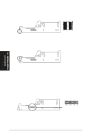
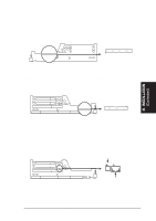
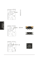
III. INSTALLATION 14. Riser Front Panel Connector (16-1 pin) This connector is used to connect the front panel display LED's and buttons to the motherboard through a ribbon cable. Riser Card Front Riser Slot Front Panel Display and Buttons The front panel displ buttons connect to th riser card through a cable. Pin 1 15. Riser Front Panel Microphone Connector (2 pin) This connector is used to connect the front panel microphone jack to the motherboard through a ribbon cable. Riser Card Front Front Panel Microphone Jack Riser Slot The front panel's 1/8inch microphone jack connects to the riser card through a ribbon cable. (Connectors) 26 ASUS TX97-N User's Manual
-
 1
1 -
2
-
3
-
4
-
5
-
6
-
7
-
8
-
9
-
10
-
11
-
12
-
13
-
14
-
15
-
16
-
17
-
18
-
19
-
20
-
 21
21 -
 22
22 -
 23
23 -
 24
24 -
 25
25 -
 26
26 -
 27
27 -
 28
28 -
 29
29 -
 30
30 -
 31
31 -
32
-
33
-
34
-
35
-
36
-
37
-
38
-
39
-
40
-
41
-
42
-
43
-
44
-
45
-
46
-
47
-
48
-
49
-
50
-
51
-
52
-
53
-
54
-
55
-
56
-
57
-
58
-
59
-
60
 |
 |

26
ASUS TX97-N User’s Manual
III. INSTALLATION
(Connectors)
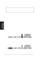
14. Riser Front Panel Connector
(16-1 pin)
This connector is used to connect the front panel display LED’s and buttons to
the motherboard through a ribbon cable.
Front Panel Display and Buttons
Riser Card Front
Pin 1
The front panel displ
buttons connect to th
riser card through a
cable.
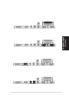
15. Riser Front Panel Microphone Connector (2 pin)
This connector is used to connect the front panel microphone jack to the moth-
erboard through a ribbon cable.
Front Panel Microphone Jack
Riser Card Front
The front panel’s 1/8inch micro-
phone jack connects to the riser
card through a ribbon cable.