Behringer CRAVE Quick Start Guide - Page 9
Step 2: Controls - patches
 |
View all Behringer CRAVE manuals
Add to My Manuals
Save this manual to your list of manuals |
Page 9 highlights
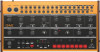
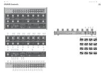
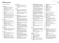
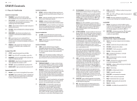
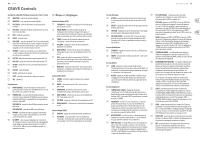
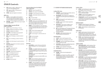
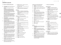
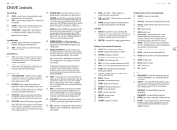
16 CRAVE CRAVE Controls (EN) Step 2: Controls Oscillator (VCO) Section (1) FREQUENCY - adjust the frequency of the oscillator, approximately one octave either side of center. (2) PULSE WIDTH - adjust the pulse width of the oscillator (when in pulse mode) from narrow, to square (center position), to wide. (3) SHAPE - select the waveform of the oscillator from pulse or reverse sawtooth. (4) OSC MOD - select the depth of modulation applied to the oscillator. (5) MOD SOURCE - select the modulation source from the envelope (or an external modulation source), or the LFO. (6) MIX - adjust the mix between the VCO output and the internal noise generator. If an external audio input is used, then this is added to the mix, instead of the noise. (7) MOD DEST - select the modulation destination from pulse width modulation, or frequency modulation. Filter (VCF) Section (8) CUTOFF - adjust the cutoff frequency of the filter. (9) MODE - select the VCF filter from low-pass or high-pass. (10) RESONANCE - adjust the amount of enhancement given to the signals at the cutoff frequency. (11) MOD SOURCE - select the modulation source of the VCF from the envelope generator or the LFO (12) VCF MOD - adjust the depth of VCF modulation. (13) MOD POLARITY- select the polarity of the VCF modulation. Output (VCA) Section (14) VOLUME - adjust the overall synthesizer output level. (15) VCA MODE - select envelope, and the VCA is modulated by the envelope. In the ON position, the VCA output is the last key played, and is independent of envelope. Envelope Section (16) ATTACK - control the amount of time taken to reach the maximum level after a key is pressed. (17) DECAY - control the amount of time taken to decay from the current level to minimum. (18) SUSTAIN - control the level of the envelope that is sustained after the attack time has been reached. (19) SUSTAIN ON/OFF - in the OFF position, the level will start to decay after the attack time is over. In the ON position, the sustain level will be held for as long as the key is held. Modulation Section (20) LFO RATE - adjust the frequency of the low frequency oscillator. The LED will flash at the LFO rate. (21) SHAPE - select the LFO waveform from squarewave or triangular wave. Utility Section (22) GLIDE - adjust the amount of Glide time (Portamento), between notes on the keyboard. (If SHIFT is held, then the knob also adjusts the "ratchet" during sequencer operation.) (23) VC MIX - adjust the VC MIX from LO/Mix 1 to HI/Mix 2. This control requires patch cords to operate, as it is outside of the internal sythesizer signal path. Sequencer Section (24) TEMPO/GATE LENGTH - this knob controls the sequencer tempo. During step editing, it also controls the GATE length. If SHIFT is held, then the knob also adjusts the SWING. (25) HOLD/REST - during pattern playback, this allows you to hold the current step. During step editing, it allows you to enter a rest. During ARP mode, it allows you to enter/ exit ARP-Hold mode. During keyboard use, it allows you to hold the keys. (A footswitch connected to the HOLD input will also do this.) (26) RESET/ACCENT - during playback, this allows you to reset the pattern back to step 1. During step editing, you can add an accent to a step. (27) ARP (SET END) - In ARP mode, an arpeggio will play, based on the held notes using the CRAVE's 13 keyboard switches. Double-press to play and hold an Arpeggio. In Sequencer mode, pressing SHIFT and SET END together, followed by a STEP switch, will allow that step to become the end of the current pattern. (28) PATTERN (BANK) - This button is used to access either the current pattern, or bank number, as follows: PATTERN: Press PATTERN, and one of the 8 LOCATION LEDs will show the current pattern number (from 1 to 8). To change to a different pattern number, keep the PATTERN button held down and press any of the STEP buttons (1 to 8), or press to increase the pattern number. BANK: Press SHIFT and PATTERN, and one of the 8 LOCATION LEDs will show the current bank number (from 1 to 8). To change to a different bank number, keep both SHIFT and BANK held down, and press any of the STEP buttons (1 to 8), or press to hincrease the bank number. (29) OCTAVE/LOCATION - these multi-colored LEDS show various details, such as the Octave, PATTERN number, BANK number, current PAGE, and GATE LENGTH. Quick Start Guide 17 (30) KEYBOARD/STEP SWITCHES - these multifunction switches allow you to view and select individual pattern steps, select a pattern number, select a pattern bank. They are used during recording of a pattern to show the current step. Active steps are illuminated with a steady red LED, and the current step flashes red. The switches are laid out as a 13-note keyboard. The octave can be moved up and down by pressing the switches, and the row of 8 LEDs will show the current octave. The switches are used to control the sequencer editing, as well as the arpeggiator operation. (31) SHIFT - this is used to access the secondary features of some of the other sequencer controls, such as SET END, BANK, SWING, KYDB, and STEP. Hold down SHIFT and the other switch at the same time. For example SHIFT + PATTERN (BANK) will show the current BANK number in the LOCATOR LEDs. (32) PAGE - each pattern can be up to 32 steps in length. This switch allows you to show each of the 4 pages of 8 steps each. The LOCATION LEDs 1 to 4, show which page you are on. If a pattern is playing, the STEP LEDs will show the steps in use on the current page. (33) PLAY/STOP - starts or stops the playback of the pattern. If SHIFT is held at the same time, then this is the start of the pattern saving procedure. (34) REC - press this to begin the recording of a new pattern. This is also used with SHIFT during the pattern saving procedure. (35) KYBD - press SHIFT + KYBD to change the sequencer to keyboard mode. (36) STEP - press SHIFT + STEP to change the sequencer to STEP mode. (37) POWER - indicates that power is supplied to the unit and the rear-panel power switch is on. MIDI Section (38) MIDI IN - this 5-pin DIN jack receives MIDI data from an external source. This will commonly be a MIDI keyboard, an external hardware sequencer, a computer equipped with a MIDI interface, etc. (39) MIDI THRU - this 5-pin DIN jack is used to pass through MIDI data received at the MIDI INPUT. Patchbay (3.5 mm TS connections) Input Section (40) OSC CV - oscillator pitch CV, at 1V/octave. (41) OSC FM - oscillator frequency modulation. (42) OSC MOD - oscillator modulation. (43) VCF CUTOFF - VCF cutoff frequency CV. (44) VCF RES - VCF Resonance CV. (45) MIX 1 - mix 1 CV in, connected internally to VC MIX. (46) MIX 2 - mix 2 CV in, connected internally to VC MIX. (47) VC MIX - VC mix control CV in, connected internally to VC MIX. (48) MULTIPLE - any signal entered here is passed out to both MULTIPLE outputs. (49) MIX CV - mix CV. (50) EXT AUDIO - external audio input. (51) TEMPO - sequencer tempo. (52) PLAY/STOP - sequencer play/stop. (53) RESET - sequencer reset. (54) HOLD - sequencer hold. (55) ENV GATE - envelope gate. (56) VCA CV - VCA CV. (57) LFO RATE - LFO frequency rate CV. Patchbay (3.5 mm TS connections) Output Section (58) MULTIPLE - copy of multiple input. (59) MULTIPLE - another copy of multiple input. (60) OSC PULSE - oscillator pulse waveform output. (61) OSC SAW - oscillator reverse sawtooth waveform output. (62) ENV - envelope output. (63) NOISE - noise output. (64) VCA/LINE - connect this 3.5 mm TS output to the line-level audio input of your system. Make sure the volume is turned down and the system is turned off before making connections. (65) PHONES - connect your headphones to this 3.5 mm TRS output. Make sure the volume is turned down before putting on headphones. (66) LFO TRI - LFO triangular waveform output. (67) LFO SQU - LFO square waveform output. (68) VC MIX - VC mix output connected internally to VC MIX. (69) ASSIGN - assign output. (70) KB CV - keyboard CV output. (71) GATE - gate output. (72) VCF - VCF output. Rear Panel (73) MIDI CHANNEL - these 4 switches allow you to set the MIDI Channel number from 1 to 16, as shown in the chart. (74) USB PORT - this USB type B jack allows connection to a computer. The CRAVE will show up as a classcompliant USB MIDI device, capable of supporting MIDI in and out. USB MIDI IN - accepts incoming MIDI data from an application. USB MIDI OUT - sends MIDI data to an application. (75) POWER - turn the synthesizer on or off. Make sure all the connections are made before turning on the unit. (76) DC INPUT - connect the supplied 12 V DC power adapter here. The power adapter can be plugged into an AC outlet capable of supplying from 100 V to 240 V at 50 Hz/60 Hz. Use only the power adapter supplied.
-
 1
1 -
2
-
3
-
 4
4 -
 5
5 -
 6
6 -
 7
7 -
 8
8 -
 9
9 -
 10
10 -
 11
11 -
 12
12 -
 13
13 -
 14
14 -
15
-
16
-
17
-
18
-
19
-
20
-
21
-
22
-
23
-
24
-
25
-
26
 |
 |