Behringer ULTRA-DRIVE PRO DCX2496 Manual - Page 8
Setup Menu, Out Configuration, Out Stereo-link - user manual
 |
View all Behringer ULTRA-DRIVE PRO DCX2496 manuals
Add to My Manuals
Save this manual to your list of manuals |
Page 8 highlights
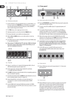
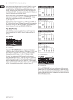
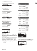
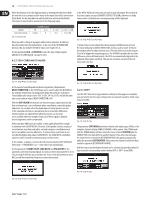
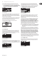
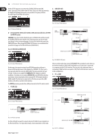
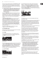
8 ULTRADRIVE PRO DCX2496 User Manual Use the buttons to the left of the output LED displays (SETUP, MUTE etc.) to enter the various menus. Most of them include several pages, which you can select with the PAGE buttons. The PARAM button selects individual parameters from one page, the data wheel edits them. Confirm new settings with OK, or cancel your selection with CANCEL. This operating structure is the same for all menus so it will not be repeated in each section of the manual. The menu name is shown at the top-left of the display. Next to this, and separated by an arrow, is the name of the current page (e.g. SETUP ➠ IN/OUT). The page number of the corresponding menu is shown on the right-hand side (e.g. 1/6 = page 1 of 6). The bottom line also shows the menu name (e.g. SETUP). For buttons IN A-C and OUT 1-6 (below the input/output LED displays), the menus for the corresponding inputs/outputs are listed (IN A, OUT 3 etc.). In addition, the output display also indicates the name of the output (e.g. SUBWOOFER, RIGHT MID etc.). 4.2 SETUP menu Use the SETUP menu to make basic adjustments necessary for the operation of your ULTRADRIVE PRO. Press the SETUP button to display the first page of this menu. 4.2.1 IN/OUT Fig. 4.1: Setup ➠ In/Out The parameter OUT CONFIGURATION selects the general operating mode; in MONO mode input A is the preset signal source for all outputs. In STEREO mode, three configurations are available. Please use inputs A and B in these modes. The display shows the OUT channels (L = LOW, M = MID and H = HIGH). Fig. 4.2: Output configuration The stereo 3-way configuration LMHLMH has input A routed to outputs 1, 2 and 3, and input B routed to outputs 4, 5 and 6. The stereo 3-way configuration LLMMHH routes input A to outputs 1, 3 and 5, and input B to outputs 2, 4 and 6. The 2-way configuration LHLHLH uses all three inputs; here, A can be routed to outputs 1 and 2, B to outputs 3 and 4, and C to outputs 5 and 6. This application is used for 3 x 2-way speaker systems or triple bi-amping (see chapter 6.3). Fig. 4.3: Setup ➠ In/Out With the OUT STEREO-LINK function you can determine whether processing with EQs, limiter, etc. is effective on the linked outputs, or whether the settings for each output can be made independently. When this function is enabled (ON), linking several outputs to each other, the display will show small connecting lines between the individual outputs.
-
 1
1 -
2
-
 3
3 -
 4
4 -
 5
5 -
 6
6 -
 7
7 -
 8
8 -
 9
9 -
 10
10 -
 11
11 -
 12
12 -
 13
13 -
14
-
15
-
16
-
17
-
18
-
19
-
20
-
21
-
22
-
23
-
24
-
25
-
26
-
27
-
28
-
29
-
30
-
31
-
32
-
33
-
34
-
35
-
36
 |
 |
