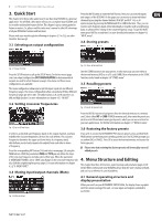
Behringer ULTRA-DRIVE PRO DCX2496 Manual - Page 9
MONO no stereo links, L1 M2 H3 L4 M5 H6, IN STEREO LINK, In the MONO configuration - settings
 |
View all Behringer ULTRA-DRIVE PRO DCX2496 manuals
Add to My Manuals
Save this manual to your list of manuals |
Page 9 highlights
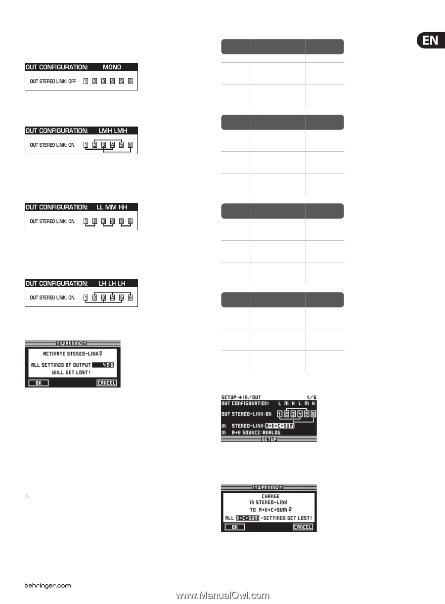
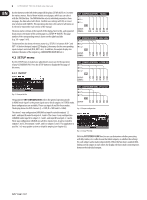
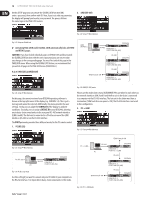
9 ULTRADRIVE PRO DCX2496 User Manual The following link options (output configurations) are available: 1. MONO (no stereo links) Fig. 4.4: Output configuration MONO 2. L(1) M(2) H(3) L(4) M(5) H(6) Fig. 4.5: Output configuration LMHLMH Link: L(1) > L(4) / M(2) > M(5) / H(3) > H(6) 3. L(1) L(2) M(3) M(4) H(5) H(6) Fig. 4.6: Output configuration LLMMHH Link: L(1) > L(2) / M(3) > M(4) / H(5) > H(6) 4. L(1) H(2) L(3) H (4) L(5) H(6) Fig. 4.7: Output configuration LHLHLH Link: L(1) > L(3) > L(5) / H(2) > H(4) > H(6) Fig. 4.8: Setup ➠ In/Out When Out Stereo Link is enabled, the unit warns you that all settings for the linked outputs will be lost, because they will be overwritten with the values of the output to be selected. Any further changes to the parameters of a specific output will be transferred directly to the linked output. However, any edits made to a LONG DELAY value (see chapters 4.2.2 and 4.5.5) will not be transferred to the other output. This parameter can be adjusted specifically for each output. SHORT DELAY settings (see chapters 4.2.2 and 4.5.5) will be transferred as long as OUT Stereo Link is on. ◊ In the MONO configuration, the Out Stereo Link function cannot be activated. OUT Configuration MONO 123456 LINK-Activation OUT Stereo Link OFF not available SHORT Delay Link (Chassis) 1 ➟ 2 ➟ 3 ➟ 4 ➟ 5 ➟ 6 Sb ➟ L ➟ LM ➟ M ➟ HM ➟ H activated by enabling "OUT STEREO-LINK" on SETUP-page 1/6 LONG Delay Link 1 ➟ 2 ➟ 3 ➟ 4 ➟ 5 ➟ 6 (Loudspeakers) Sb ➟ L ➟ LM ➟ M ➟ HM ➟ H activated by enabling "LINK" on OUT-page 8/8 OUT Configuration OUT Stereo Link SHORT Delay Link (Chassis) LONG Delay Link (Loudspeakers) LMH LMH 123 456 1 ➟ 4 2 ➟ 5 3 ➟ 6 L ➟ L M ➟ M H ➟ H 1 ➟ 4 2 ➟ 5 3 ➟ 6 L ➟ L M ➟ M H ➟ H 1 ➟ 2 ➟ 3 4 ➟ 5 ➟ 6 L ➟ M ➟ H L ➟ M ➟ H LINK-Activation activated by enabling "OUT STEREO-LINK" on SETUP-page 1/6 activated by enabling "OUT STEREO-LINK" on SETUP-page 1/6 activated by enabling "LINK" on OUT-page 8/8 OUT Configuration OUT Stereo Link SHORT Delay Link (Chassis) LONG Delay Link (Loudspeakers) LL MM HH 12 34 56 1 ➟ 2 3 ➟ 4 5 ➟ 6 L ➟ L M ➟ M H ➟ H 1 ➟ 2 3 ➟ 4 5 ➟ 6 L ➟ L M ➟ M H ➟ H 1 ➟ 2 ➟ 3 4 5 ➟ 6 L ➟ L M ➟ M H ➟ H LINK-Activation activated by enabling "OUT STEREO-LINK" on SETUP-page 1/6 activated by enabling "OUT STEREO-LINK" on SETUP-page 1/6 activated by enabling "LINK" on OUT-page 8/8 OUT Configuration OUT Stereo Link SHORT Delay Link (Chassis) LONG Delay Link (Loudspeakers) LH LH LH 12 34 56 1 ➟ 3 ➟ 5 2 ➟ 4 ➟ 6 L ➟ L ➟ L H ➟ H ➟ H 1 ➟ 3 ➟ 5 2 ➟ 4 ➟ 6 L ➟ L ➟ L H ➟ H ➟ H 1 ➟ 2 3 ➟ 4 5 ➟ 6 L ➟ H ➟ L H ➟ L ➟ H LINK-Activation activated by enabling "OUT STEREO-LINK" on SETUP-page 1/6 activated by enabling "OUT STEREO-LINK" on SETUP-page 1/6 activated by enabling "LINK" on OUT-page 8/8 Tab. 4.1: Survey of all OUT LINK configurations Fig. 4.9: Setup ➠ In/Out The inputs can also be linked using the parameter IN STEREO LINK. Thus, all settings of one input can be transferred to another input, or to all inputs. Fig. 4.10: Setup ➠ In/Out
-
 1
1 -
2
-
3
-
 4
4 -
 5
5 -
 6
6 -
 7
7 -
 8
8 -
 9
9 -
 10
10 -
 11
11 -
 12
12 -
 13
13 -
 14
14 -
15
-
16
-
17
-
18
-
19
-
20
-
21
-
22
-
23
-
24
-
25
-
26
-
27
-
28
-
29
-
30
-
31
-
32
-
33
-
34
-
35
-
36
 |
 |