Behringer iNUKE NU3000DSP Manual - Page 15
Applications
 |
View all Behringer iNUKE NU3000DSP manuals
Add to My Manuals
Save this manual to your list of manuals |
Page 15 highlights
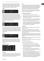
15 iNUKE NU6000DSP/NU3000DSP/NU1000DSP User Manual 2. Click on the Recall button in the upper left of the Amp Presets section. The selected preset's name will appear in the text box next to the Recall button. All settings contained in the preset will automatically deploy. Saving a preset to the amp's internal memory 1. Select a destination for the preset by clicking on a slot in the preset list. (If you save your preset to a slot already holding a stored preset, the stored preset will be replaced by your new preset.) 2. Type your new preset's name into the text box to the right of the Recall button. 3. Click on the Store button to store your preset in the selected slot in the preset list. Your new preset's name will appear in the selected slot in the preset list. Amp Connection Renaming an amplifier 1. Type the new amplifier name directly into the text box to the left of the Rename Amp virtual button near the bottom of the Amp Connection section. 2. Click on the Rename Amp virtual button. The new amplifier name will appear in the Amp Name column of the amplifier list. Locking the amplifier 1. Type a 4-character lock code of your choosing directly into the Lock Code window near the bottom of the Amp Connection section. (The Lock function requires a new lock code every time you lock the amplifier.) 2. Click on the Lock virtual button at the bottom right of the Amp Connection section. The Lock virtual button will turn red to indicate the amplifier front panel has been locked. 3. Clear the 4-character code from the Lock Code window if you desire extra security. The Amp Connection section tells you which iNUKE amplifier you have connected to the software, as well as options for naming your iNUKE amp and for setting up a code to lock the amplifier's front panel and prevent tampering (the amp can still be edited from your laptop using the Amp Remote software). For the current edition of the BEHRINGER Amp Remote software, only one iNUKE amplifier can appear at any one time in the amplifier list and be recognized by the software. Similarly, the IP address function can only be deployed with EUROCOM installed sound power amplifiers. Connecting to an amplifier ◊ this procedure assumes you already have an iNUKE amplifier connected to your computer, and that you are switching to another iNUKE amplifer. Usually, the Amp Remote software will automatically detect a USB-connected iNUKE amp and then ask if you wish to connect to the detected amplifer. 1. Click on the Connect virtual button near the bottom of the Amp Connection section of the Setup tab. The software will disconnect from the current amplifer, clear the amplifier from the list in the Amp Connection section, and clear all presets from the Amp Presets list. 2. Press the Search virtual button near the top of the Amp Connection section, above and to the left of the amplifier list window. When the software finds your newly-connected iNUKE amp, the amplifier will appear in the amplifier list window, and the amp's internal presets will populate the Amp Presets list. The software will also launch a confirmation window asking if you wish to connect to the detected amplifier. 3. Press the Connect virtual button in the confirmation window to finalize the connection. Unlocking the amplifier 1. Type the amplifier's 4-character lock code into the Lock Code window near the bottom of the Amp Connection section. 2. Click on the Unlock virtual button located directly to the right of the Lock Code text box. The Unlock virtual button will light up yellow to indicate the amplifier is unlocked, while the Lock button will change colors from red to gray. The characters in the Lock Code text box will disappear and be replaced by asterisks. 4. Applications 4.1 Bi-amping Bi-amping splits a mono signal into upper and lower frequency bands, and then assigns each frequency band to separate speaker cabinets. A subwoofer typically takes the low frequency range. By splitting the signal this way, the speakers work more efficiently, and you can achieve a cleaner overall sound. Setting up hardware for bi-amping 1. Run a 4-pole speaker cable with professional twist-locking connectors from OUTPUT CH A to the subwoofer. (The subwoofer receives its low-frequency signal from Channel B using poles 2+ and 2-, while the middle and upper frequency ranges use Channel A via poles 1+ and 1-.) 2. Set the subwoofer into BIAMPING mode. 3. Run a 2-pole speaker cable with professional twist-locking connectors from the subwoofer to the other speaker. Programming DSP parameters for bi-amping 1. Choose the BIAMP1 setting on the Amp Mode screen. 2. Go to the XOVER screen using the UP/DOWN buttons to set appropriate high/low crossover frequencies. 3. In Channel A#1, choose your high-pass filter type (HPtype: BUT6, BUT12, BES12, etc.) and set the cutoff frequency (HPfreq) to approximately 100 Hz. Deactivate the low-pass filter (LPtype: OFF) on this channel and set the gain level (Gain) to suit your system. 4. In Channel B#1, choose your low-pass filter type (LPtype: BUT6, BUT12, BES12, etc.) and set the cutoff frequency (LPfreq) to approximately 100 Hz. Deactivate the high-pass filter (HPtype: OFF) on this channel and set the gain level (Gain) to suit your system.
-
 1
1 -
2
-
3
-
4
-
5
-
6
-
7
-
8
-
9
-
 10
10 -
 11
11 -
 12
12 -
 13
13 -
 14
14 -
 15
15 -
 16
16 -
 17
17 -
 18
18 -
 19
19 -
 20
20 -
21
-
22
 |
 |
