Behringer iNUKE NU3000DSP Manual - Page 17
Installation
 |
View all Behringer iNUKE NU3000DSP manuals
Add to My Manuals
Save this manual to your list of manuals |
Page 17 highlights
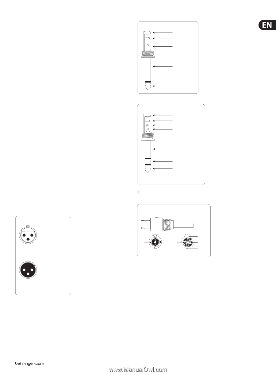
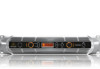
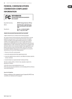
17 iNUKE NU6000DSP/NU3000DSP/NU1000DSP User Manual 5. Installation 5.1 Rack mounting Your iNUKE amplifier fits into a 19" rack and requires two rack units. Install into the rack using four attaching screws and washers for the front panel. Reinforce the back panel, especially if you will be taking the iNUKE on the road. Make sure enough cool air reaches the rack, especially when other rack equipment emanates a lot of heat. The iNUKE amplifiers circulate heat from the rear to the front vents to relieve heat inside the rack enclosure. Fan speed adjusts automatically to assure safe operation. Never block ventilation openings. Should internal temperature reach extreme values, the unit will shut down automatically. Unbalanced ¼" TS connector strain relief clamp sleeve tip sleeve (ground/shield) tip (signal) 5.2 Connections 5.2.1 Audio inputs Each channel input uses combo jacks that can accept both balanced XLR and ¼" TRS stereo connectors, as well as unbalanced ¼" TS connectors. To deploy XLR connectors for unbalanced signals, bridge pins 1 and 3; mono ¼" TS connectors do not require any alteration to carry unbalanced signals. When working with balanced signals, please make sure to exclusively use balanced cables. One unbalanced cable in the signal chain can change a balanced signal into an unbalanced signal. Balanced ¼" TRS connector strain relief clamp sleeve ring tip sleeve ground/shield 5.2.2 Outputs Your iNUKE amplifier requires two twist-locking professional speaker connectors. These professional speaker connectors were developed specially for driving high-powered speakers. The connectors snap in securely, prevent electric shock, and ensure correct polarity. Inside the professional speaker connector, the 1+ pin (see figure) carries signal from either one or both channels, and this pin therefore suits mono-bridged operation (use pins 1+ and 2+). The lower connector, the 2+ pin, carries signal from CH B only. ring cold (-ve) tip hot (+ve) For connection of balanced and unbalanced plugs, ring and sleeve have to be bridged at the stereo plug. ◊ Whenever possible, use thick and short speaker cables to minimize power loss. Never lay output cables near input cables. Professional speaker connector (compatible with Neutrik Speakon connectors) Balanced use with XLR connectors 21 3 input 1 = ground/shield 2 = hot (+ve) 3 = cold (-ve) 12 3 output For unbalanced use, pin 1 and pin 3 have to be bridged 1+ 1+ 2- 1- 1- 2- 2+ front view 2+ rear view 5.2.3 Connecting to the mains Always connect your iNUKE amplifier to the voltage specified on the rear of the device. Connecting the amp to an incorrect voltage can permanently damage your amp. Before powering up the amplifier, double-check all connections and fully lower the gain setting.
-
 1
1 -
2
-
3
-
4
-
5
-
6
-
7
-
8
-
9
-
10
-
11
-
 12
12 -
 13
13 -
 14
14 -
 15
15 -
 16
16 -
 17
17 -
 18
18 -
 19
19 -
 20
20 -
 21
21 -
 22
22
 |
 |