Behringer iNUKE NU3000DSP Manual - Page 4
Introduction, Control Elements - power amp
 |
View all Behringer iNUKE NU3000DSP manuals
Add to My Manuals
Save this manual to your list of manuals |
Page 4 highlights
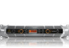
4 iNUKE NU6000DSP/NU3000DSP/NU1000DSP User Manual (1) (3) (4) (7) (2) (5) (6) (8) (9) Front panel control elements 1. Introduction 1.1 Before you get started 1.1.1 Shipment Your iNUKE amplifier was carefully packed at the factory, and the packaging is designed to protect the unit from rough handling. Nevertheless, we recommend that you carefully examine the packaging and its contents for any signs of physical damage that may have occurred during transit. • If the unit is damaged, please do NOT return it to BEHRINGER, but notify your dealer and the shipping company immediately. Otherwise, claims for damage or replacement may not be granted. 1.1.2 Initial operation Please make sure the unit is provided with sufficient ventilation, and never place your iNUKE amp on top of other heat-emanating equipment or in the vicinity of a heater to avoid the risk of overheating. The mains connection is made via the enclosed power cord and a standard IEC receptacle. It meets all international safety certification requirements. • Please make sure that all units have a proper ground connection. For your own safety, never remove or disable the ground conductor from the unit or the AC power cord. • The sound quality may diminish within the range of powerful broadcasting stations and high-frequency sources. Increase the distance between the transmitter and the device and use shielded cables for all connections. 1.1.3 Online registration Please register your new BEHRINGER equipment right after your purchase by visiting http://behringer.com and read the terms and conditions of our warranty carefully. Should your BEHRINGER product malfunction, it is our intention to have it repaired as quickly as possible. To arrange for warranty service, please contact the BEHRINGER retailer from whom the equipment was purchased. Should your BEHRINGER dealer not be located in your vicinity, you may directly contact one of our subsidiaries. Corresponding contact information is included in the original equipment packaging (Global Contact Information/European Contact Information). Should your country not be listed, please contact the distributor nearest you. A list of distributors can be found in the support area of our website (http://behringer.com). Registering your purchase and equipment with us helps us process your repair claims more quickly and efficiently. 2. Control Elements 2.1 Front panel (1) USB connection enables firmware updates and control over parameters via computer. Please visit Behringer.com to download DSP control software for your computer. The USB port is for amplifier configuration only. (2) SIGNAL and LIMIT LEDs display the signal level for each channel. Reduce the input gain if the red LIMIT LED lights up continuously. (3) CH A/CH B CONTROLS adjust the input level. To increase signal gain, rotate the knobs clockwise; to reduce the gain, rotate the knobs counter-clockwise. (4) PROCESS button steps through the DSP processing modules. (5) SETUP button steps through parameters within DSP processing modules. (6) LCD SCREEN displays the current DSP module and parameter settings. (7) UP/DOWN/EXIT buttons step through DSP modules and parameters or exit to the top-level iNUKE screen (center button). (8) SELECT encoder knob toggles between Graphic and Edit modes (when pressed) and changes parameter values (when rotated). (9) POWER button turns the amplifier on and off.
-
 1
1 -
 2
2 -
 3
3 -
 4
4 -
 5
5 -
 6
6 -
 7
7 -
 8
8 -
 9
9 -
 10
10 -
11
-
12
-
13
-
14
-
15
-
16
-
17
-
18
-
19
-
20
-
21
-
22
 |
 |
