Bernina 531 Manual - Page 14
Cleaning, Oiling
 |
View all Bernina 531 manuals
Add to My Manuals
Save this manual to your list of manuals |
Page 14 highlights
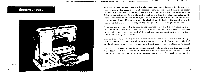
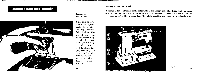
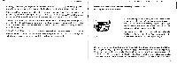
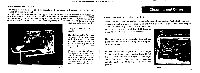
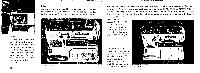
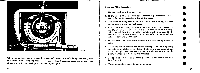
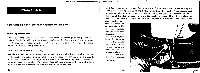
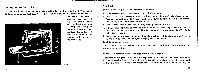
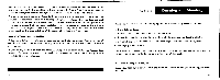
Thread Tension Box Fig. 9 The thread tension is designed to operate without special adjustment for all normal sewing and mending work. A sight hole is provided on the upper portion of the thread tension box, which is equipped with a reference line 34 on either side. Below this reference line is situated the white ring 35 on the adjusting nut 36, marking the normal adjustment of the thread tension. To set the tension turn adjusting nut 36 until the white line in level with the reference line 34. 37 22 Fixing the Slide-on Table Fig. 10 The slide-on table 37 is ac- commodated in the rear wall of the carrying case and held there by means of a bolt. Swivelling the bolt 4 to the right releases the table. When the table is slid onto the free arm, make sure that the locking lever 3S is pointing to the right. In order to clamp the table to the free arm rigidly, the lever is moved to the left. Fit. 10 Cleaning and Oiling Cleaning the Machine rigs. 11 and 12 Fluff is collected during sewing particularly around the shuttle. Such fluff may detri- mentally affect. the proper function of any machine and it is absolutely necessary to remove it frequently. From time to time, re- move cover plate 1 so that the fluff forming under the needle plate can be removed. (4] The cover plate is accordingly designed for quick removal, so that cleaning and oiling can be effected easily. To remove the cover plate, open the hinged 39 plate and depress the releasing lever 40 (cf, Fig. 11) with the index finger of the right hand. The presser foot need not be removed but the needle should be placed in its raised position. Fig. 11 23
-
 1
1 -
2
-
3
-
4
-
5
-
6
-
7
-
8
-
 9
9 -
 10
10 -
 11
11 -
 12
12 -
 13
13 -
 14
14 -
 15
15 -
 16
16 -
 17
17 -
 18
18 -
 19
19 -
20
-
21
-
22
-
23
-
24
-
25
-
26
-
27
-
28
-
29
-
30
-
31
-
32
-
33
-
34
-
35
-
36
-
37
-
38
-
39
-
40
-
41
-
42
-
43
-
44
-
45
-
46
-
47
-
48
-
49
-
50
-
51
-
52
-
53
-
54
 |
 |
